Piston-cam engine

a technology of piston cam engine and cam body, which is applied in the direction of machines/engines, connecting rods, shafts and bearings, etc., can solve the problems of prior modified systems that have not provided the leakage tightness found in reciprocating, variations of such prior engines have not provided a suitable solution, etc., to achieve high efficiency and torque, and reduce potential wear and force

Inactive Publication Date: 2005-10-06
CHANEY RAY O
View PDF6 Cites 4 Cited by
  • Summary
  • Abstract
  • Description
  • Claims
  • Application Information

AI Technical Summary

Benefits of technology

[0008] Still another object is to provide a piston-cam engine of relatively high efficiency and torque.
[0009] Another object of the invention is to provide at least one slave piston which cooperates with a drive piston to reduce potential wear and force exerted on the drive piston.

Problems solved by technology

Prior modified systems have failed to provide suitable leak tightness found in reciprocating cylindrical pistons.
Variations of such prior engines fail to provide a suitable solution to prevent potential wear within the engine.

Method used


Image

  • Piston-cam engine
  • Piston-cam engine
  • Piston-cam engine

Examples


Embodiment Construction

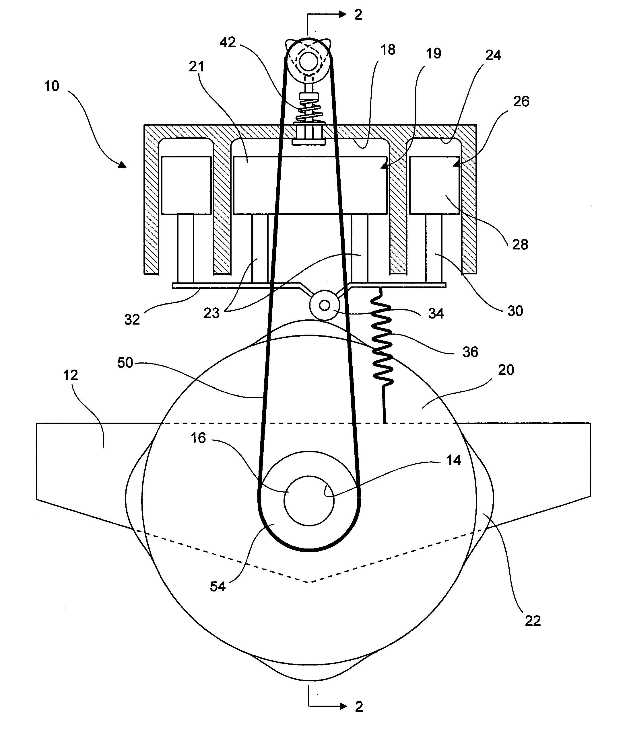
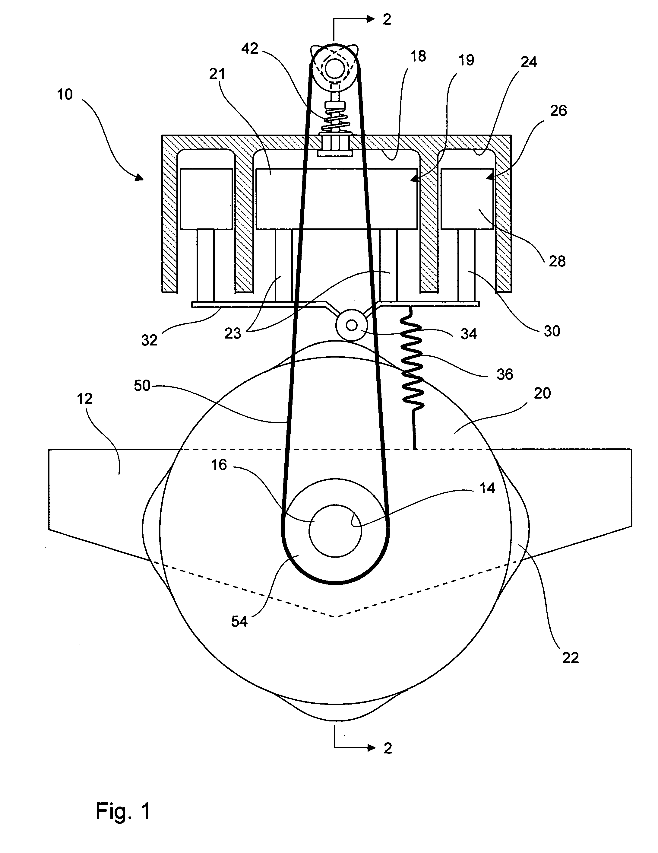
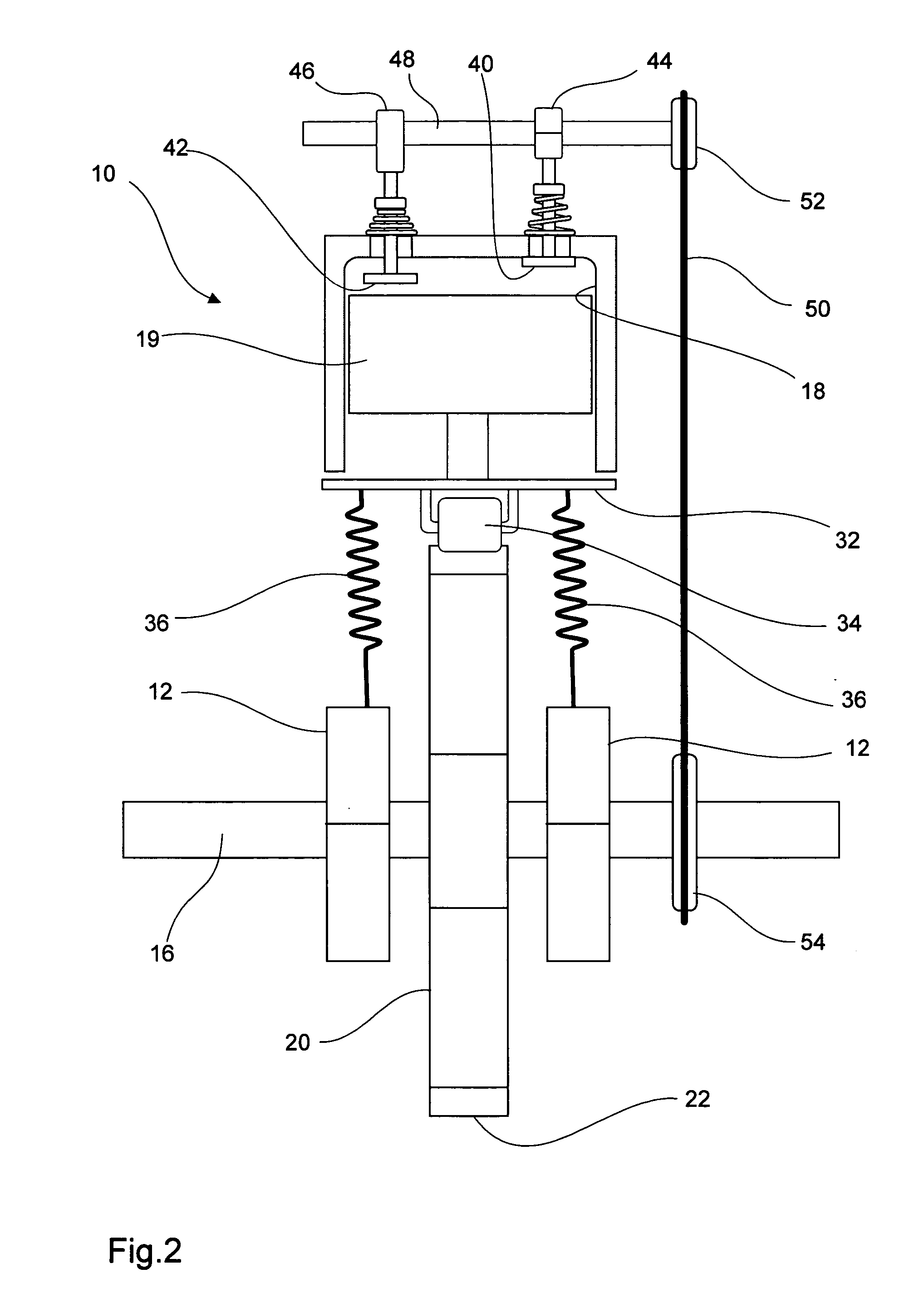
[0019] Referring now to the drawings in detail, where-in like characters of reference denote corresponding parts, the piston-cam engine is generally referred to by the numeral 10. The piston-cam engine 10 includes a support frame 12 mounted to a vehicle frame (not shown), for example, and has a generally cylindrical open bearing surface 14, to movably receive a drive shaft 16 the purpose of which will be presently apparent.

[0020] A drive cylinder 18 is operably disposed adjacent the drive shaft 16 which supports a cam 20 thereon which may be keyed, splined or otherwise rigidly connected thereto. A drive piston 19 is operably disposed within the cylinder 18. The drive piston 19 includes a head 21 and shafts 23. While there are two shafts 23, it is contemplated that one may be employed.

[0021] As illustrated in the drawings, the cam 20 includes a periphery face which is provided with a plurality of lobes 22. Here, there are four lobes 22 shown wherein the number of cycles in the engi...


PUM


Abstract

A piston-cam engine includes a drive cylinder, a drive piston operably disposed therein having a piston head and a shaft, a support frame having a drive shaft rotatably movably connected thereto, a cam having a peripheral surface and having a plurality of lobes thereon, a roller member connected to the piston shaft and adapted for engagement with the peripheral surface of the cam, and a biasing element for biasing the roller member continuously against the peripheral surface of the cam. A support drive plate interconnects the piston shaft and the roller member and one or more slave cylinder(s) is provided adjacent the drive cylinder and has a slave piston operably disposed therein and has a piston head and a shaft, wherein the slave piston shaft is connected to the support drive plate to absorb part of a force exerted on the support plate during operation of the engine.

Description

BACKGROUND OF THE INVENTION [0001] 1. Field of Invention [0002] This invention relates to combustion engines with improvements therein. Particularly, the engine embodies a novel cam drive mechanism to increase power. [0003] 2. Prior Art [0004] Conventional reciprocating piston type engines adopt a crankshaft and connecting-rod mechanism. In order to gain efficiency in power in the combustion engines, these type of engines have been modified to eliminate the crank shaft and connecting rod mechanism and made the engine more compact. [0005] Prior modified systems have failed to provide suitable leak tightness found in reciprocating cylindrical pistons. Prior engine modifications have also employed a single shaft and connecting-rod mechanism to the piston for driving the same within the cylinder. These prior modifications use moving connecting rods. Variations of such prior engines fail to provide a suitable solution to prevent potential wear within the engine. SUMMARY OF THE INVENTION ...

Claims


Application Information

Patent Timeline
IPC IPC(8): F02B75/18F02B75/22F02B75/32
CPCF02B75/32F02B75/222
Inventor CHANEY, RAY O.
Owner CHANEY RAY O
Why Eureka
Try Eureka