
Self-propelled cleaner

a cleaner and self-propelled technology, applied in the direction of process and machine control, distance measurement, instruments, etc., can solve the problems of complicated equipment and difficult popularization of the use of i

Inactive Publication Date: 2005-09-29
FUNAI ELECTRIC CO LTD
View PDF0 Cites 24 Cited by
  • Summary
  • Abstract
  • Description
  • Claims
  • Application Information

AI Technical Summary

Benefits of technology

[0013] Although the self-propelled cleaner can generate geographical information in various ways, a user interface which enables the user to recognize the geographical information at a glance will require a means to display a map and a means to receive user instructions, and the like. This would be costly and laborious. Besides, while the self-propelled cleaner is generating geographical information, it does not always travel at a user-specified time in a user-specified place. It would be very inconvenient if the user has to wait to give an instruction until the cleaner reaches a desired position. In contrast, when a marker which provides required positional data is installed, positional data can be preset very easily.
[0029] Taking full advantage of the special feature as a self-propelled machine, it is possible to check the condition of a cared person and notify a person outside of it without the need for many additional components.

Problems solved by technology

Since the above conventional nursing support robots are intended only for nursing, they use complicated equipment.
Therefore, they are expensive and it is difficult for them to be popularly used.

Method used


Image

  • Self-propelled cleaner
  • Self-propelled cleaner
  • Self-propelled cleaner

Examples


Embodiment Construction

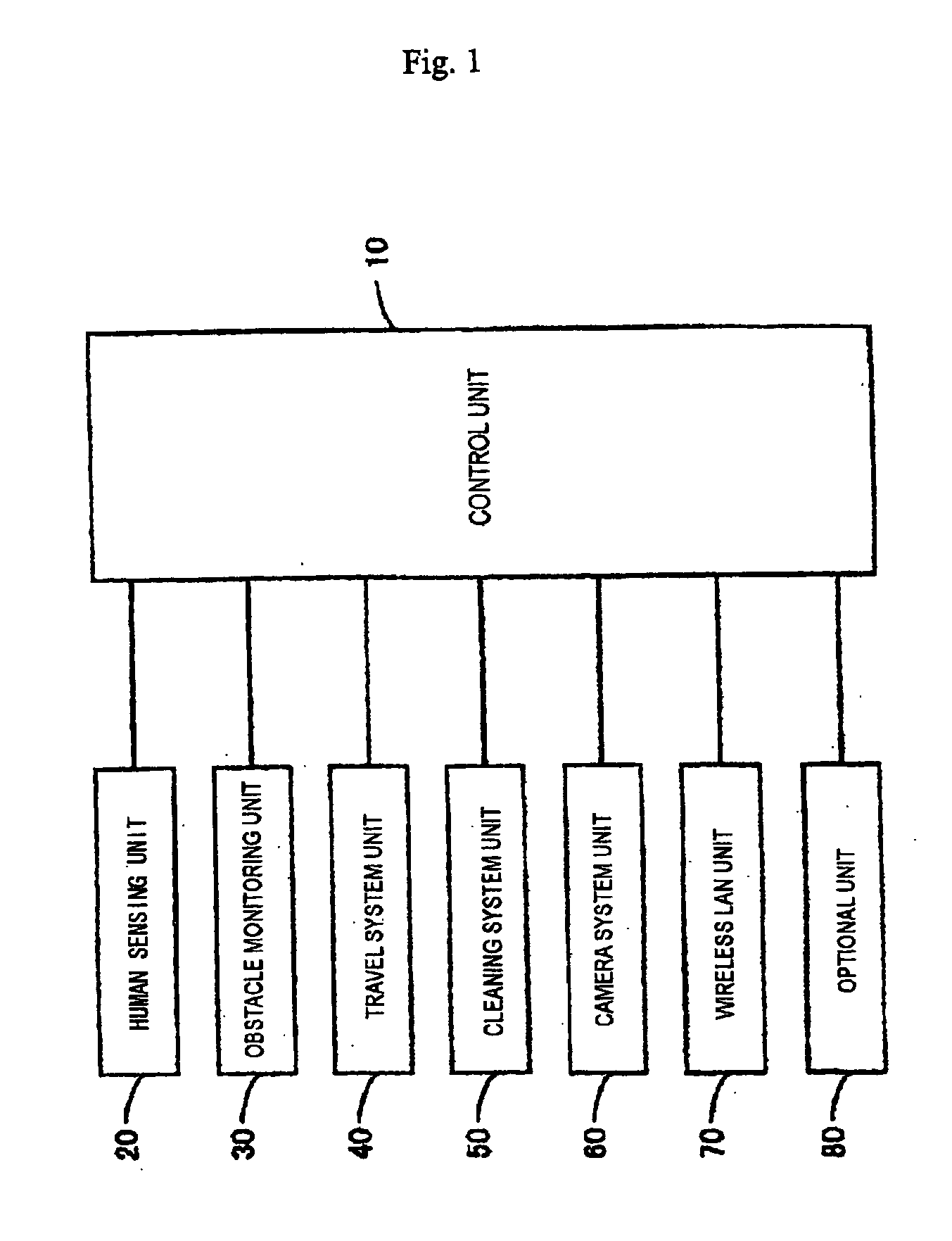
[0047] As shown in FIG. 1, according to this invention, the cleaner includes a control unit 10 to control individual units; a human sensing unit 20 to detect a human or humans around the cleaner; an obstacle monitoring unit 30 to detect an obstacle or obstacles around the cleaner; a traveling system unit 40 for traveling; a cleaning system unit 50 for cleaning; a camera system unit 60 to take a photo of a given area; a wireless LAN unit 70 for wireless connection to a LAN; and an optional unit 80 including an additional sensor and the like. The body of the cleaner has a low profile and is almost cylindrical.

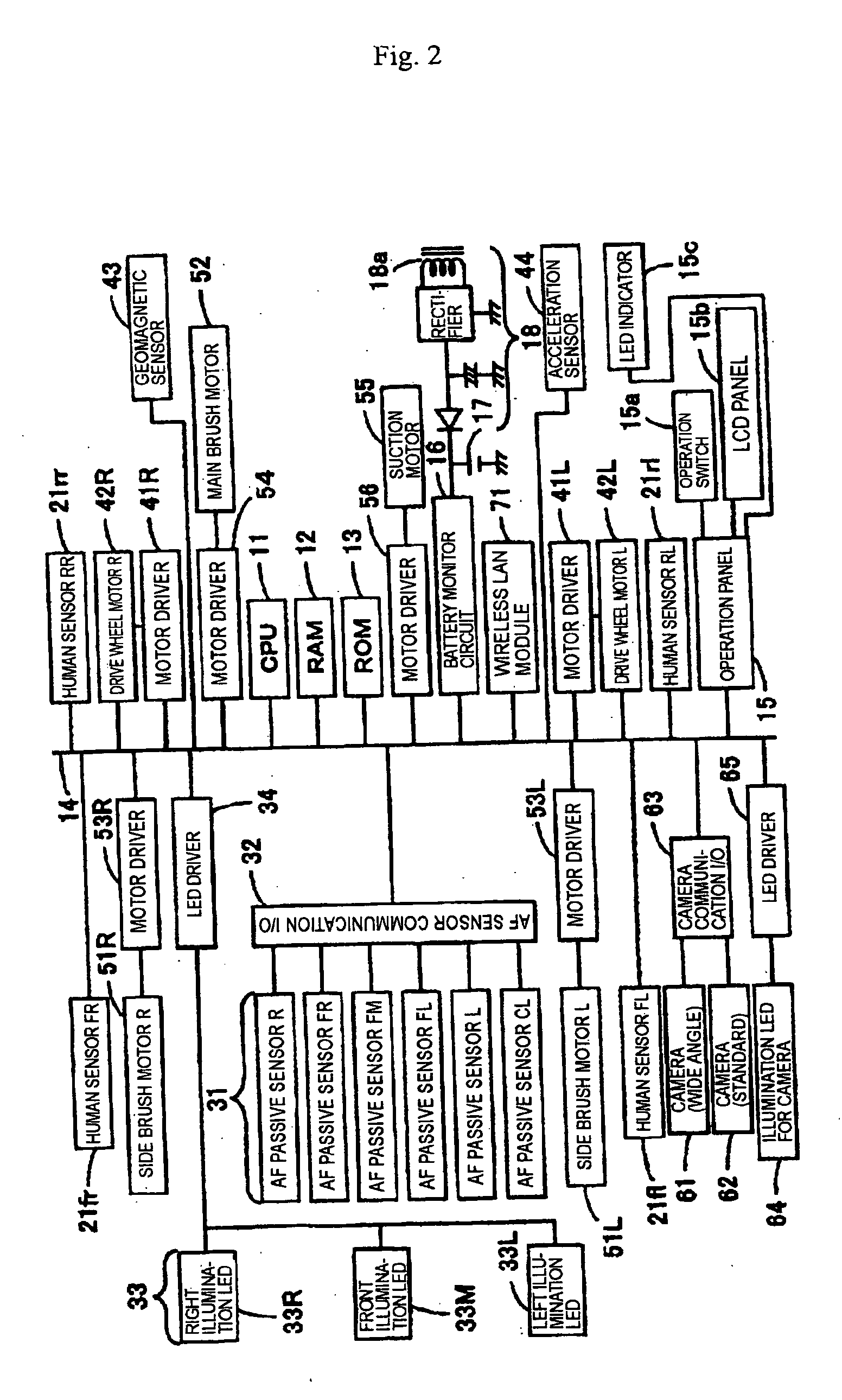
[0048] As shown in FIG. 2, a block diagram showing the electrical system configuration for the individual units, a CPU 11, a ROM 13, and a RAM 12 are interconnected via a bus 14 to constitute a control unit 10. The CPU 11 performs various control tasks using the RAM 12 as a work area according to a control program stored in the ROM 13 and various parameter tables. The control pr...


PUM


Abstract

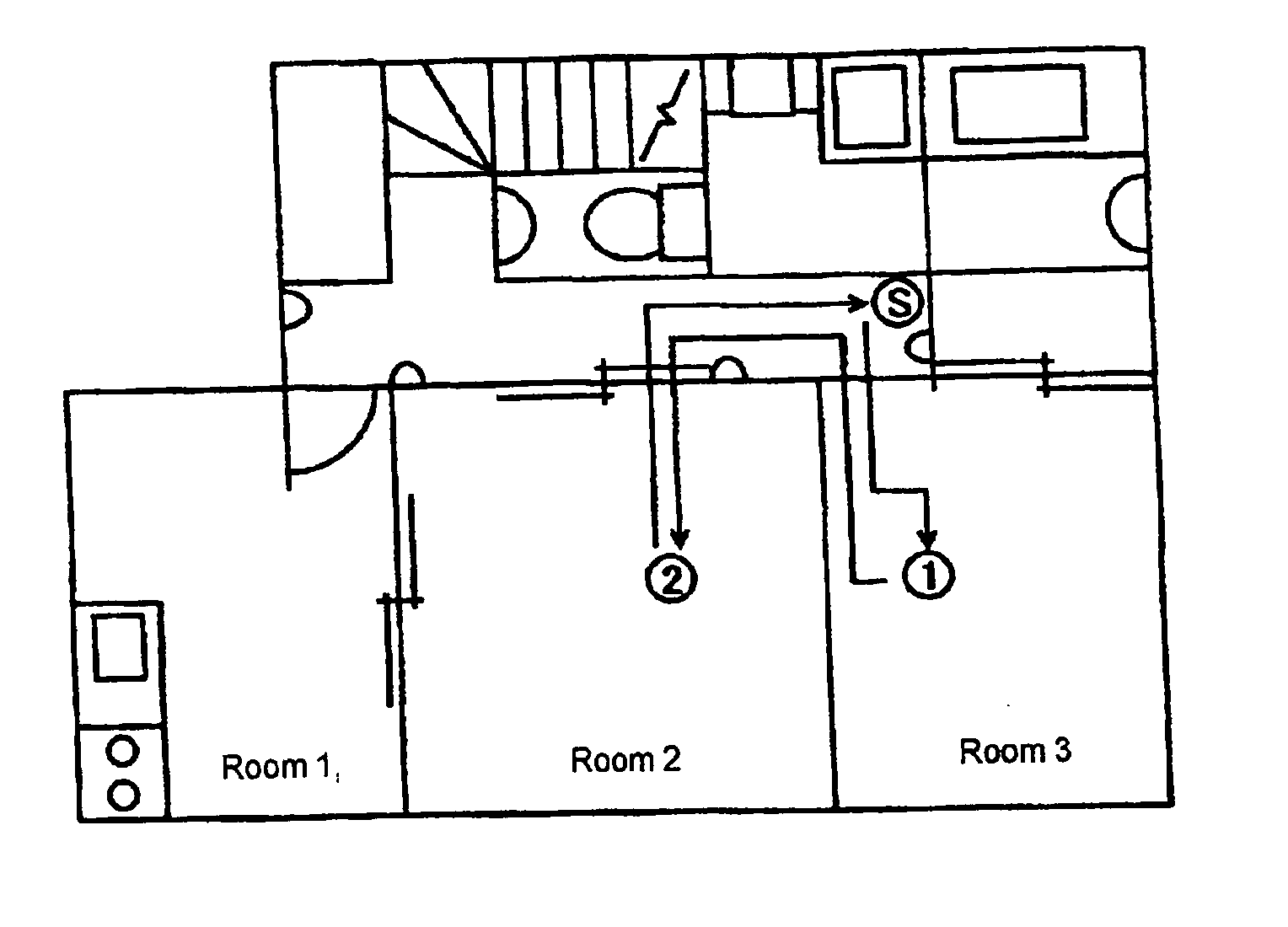
Conventional nursing support robots, which are intended only for nursing, use complicated equipment. Therefore, they are expensive and it is difficult for them to be popularly used. According to the present invention, when a robot system decides at step S440 that it is time preset on a timer, it calculates a travel route from the standby position to a first cared person's location at step S446 and moves to that location at step S448 and asks the person a question and judges the answer (steps S450 to S458). If the answer is normal, it calculates the travel route from the first cared person's location to the second cared person's at step S446 and moves to the second cared person's location at step S448 and asks a question and judges the answer (steps S450 to S458). If the answer is not normal at a cared person's location, the system compiles nursing data on that person at steps S462 to S466 and transmits it through a wireless LAN at step S468. When the nursing patrol process for all persons to be checked for is finished, the system returns to its original standby position in a hall at step S462.

Description

BACKGROUND OF THE INVENTION [0001] 1. Field of the Invention [0002] This invention relates to a self-propelled cleaner comprising a body with a cleaning mechanism and a drive mechanism capable of steering and driving the cleaner. [0003] 2. Description of the Prior Art [0004] The following nursing support robots have been known: a nursing support robot which asks a question, receives an answer and notifies the outside of an abnormality if the answer is not normal, as disclosed in JP-A No. 574 / 2002 (Patent document 1); and a nursing support robot which transmits information on the appearance of a person to be cared for as an image, as disclosed in JP-A No.234681 / 1998 (Patent document 2). [0005] Since the above conventional nursing support robots are intended only for nursing, they use complicated equipment. Therefore, they are expensive and it is difficult for them to be popularly used. SUMMARY OF THE INVENTION [0006] This invention has been made in view of the abovementioned problem ...

Claims


Application Information

Patent Timeline
IPC IPC(8): A47L9/00A47L9/28A61G12/00G05D1/02
CPCG05D1/0242G05D1/0246G05D2201/0203G05D1/027G05D1/0272G05D1/0259G05D1/0274
Inventor TANI, TAKAO
Owner FUNAI ELECTRIC CO LTD
Learn More