
Fast faraday cup with high bandwidth

a fast faraday cup and high bandwidth technology, applied in the field of fast faraday cup system, can solve the problems of strict bandwidth limitation, other limitations of fast faraday cups, and bandwidth limitation on the order of 6 ghz, and achieve the effect of improving the bandwidth, dispersion and noise immunity of the system

Inactive Publication Date: 2005-09-29
UT BATTELLE LLC
View PDF9 Cites 72 Cited by
  • Summary
  • Abstract
  • Description
  • Claims
  • Application Information

AI Technical Summary

Benefits of technology

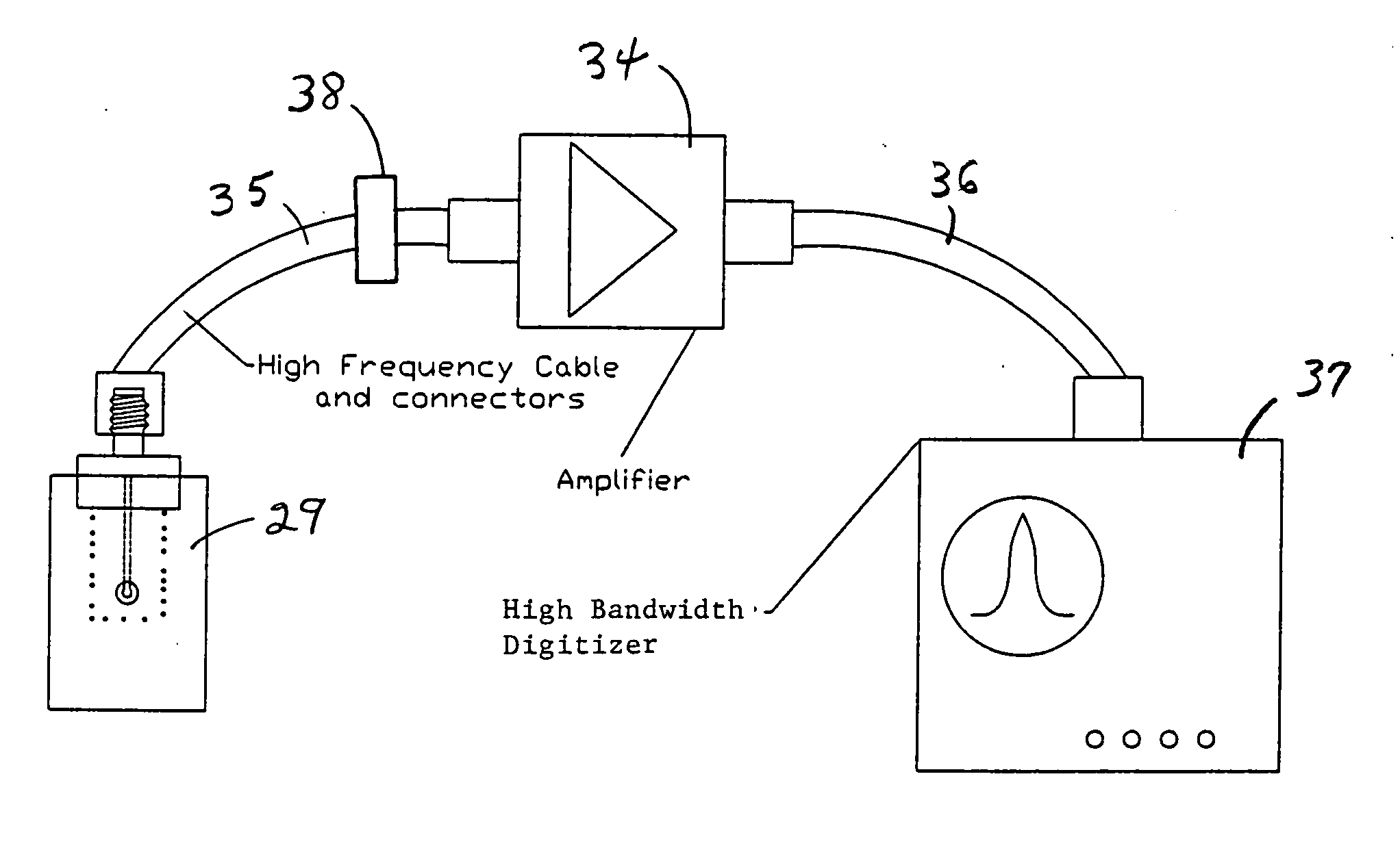
[0011] The invention is a circuit card stripline Fast Faraday cup system for measuring the structure of a charged particle beam that includes a first groundplane; a first dielectric bonded to the first groundplane; a conductor bonded to the first dielectric wherein a portion of the conductor is used as the beam target; a second dielectric bonded to the conductor by means of a bonding dielectric, the bonding dielectric having the same dielectric constant as the first dielectric; a second groundplane bonded to the second dielectric, the second dielectric and the second groundplane having a channel for the unimpeded passage of the beam to the beam target; a high bandwidth digitizer connected to the conductor, the high bandwidth digitizer electrodynamically matched to the conductor and the beam target; and electroplated stitching of the first groundplane to the second groundplane to prevent the occurrence of a resonance condition between the first and second groundplanes.

Problems solved by technology

Previous measurements of Fast Faraday cup devices used to measure the longitudinal microstructure of charged particle beams in a vacuum environment have shown a bandwidth limitation on the order of 6 GHz.
Fast Faraday cups have been shown to have other limitations as well.
The improper choice of connectors can result in strict bandwidth limitations.
The cup designs have also had fabrication problems.
For example, when much of the electromagnetic shield fabrication and assembly for the low energy beams was done by hand, the bandwidth has been limited.
Also, the use of surface mount resistors to electrodynamically match to the cup is particularly harmful when measuring weak signals because the resistors have bandwidth limitations in addition to introducing loss.

Method used


Image

  • Fast faraday cup with high bandwidth
  • Fast faraday cup with high bandwidth
  • Fast faraday cup with high bandwidth

Examples


Embodiment Construction

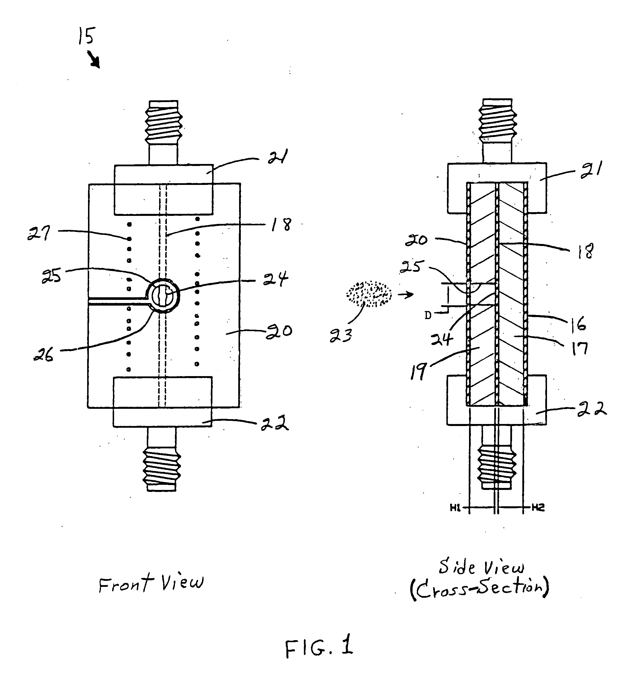
[0018]FIG. 1 illustrates front and cross-section views of a preferred two-connector embodiment of the invention. In FIG. 1, the Fast Faraday cup 15 is designed in a four-layer stripline circuit card configuration that comprises a bottom ground layer 16, a dielectric layer 17, a trace 18, a portion of which (24) is the actual cup or beam target, another dielectric layer 19, and a top ground layer 20. The two grounds 16, 20 surround the circuit card. These grounds shield the target 24 and trace 18 from the harsh electrodynamic environment, and also reduce the noise of the charged particle beam 23 while guiding the induced signal on the trace. The device is fabricated with two edge launch connectors 21, 22 that are broadband matched to the circuit card and are used for retrieving the signal. If it is desired to use only one of the connectors, the unused end of the trace 18 can be terminated in the transmission line impedance of, for example, 50 ohms. In FIG. 1, the dimension D is the d...


PUM

PropertyMeasurementUnit
impedanceaaaaaaaaaa
dielectric constantaaaaaaaaaa
structureaaaaaaaaaa

Abstract

A circuit card stripline Fast Faraday cup quantitatively measures the picosecond time structure of a charged particle beam. The stripline configuration maintains signal integrity, and stitching of the stripline increases the bandwidth. A calibration procedure ensures the measurement of the absolute charge and time structure of the charged particle beam.

Description

STATEMENT REGARDING FEDERALLY SPONSORED RESEARCH OR DEVELOPMENT [0001] The United States Government has rights in this invention pursuant to contract no. DE-AC05-00OR22725 between the United States Department of Energy and UT-Battelle, LLC.FIELD OF THE INVENTION [0002] The present invention relates to devices for measuring the longitudinal microstructure of a charged particle beam to a very high bandwidth, and more particularly relates to a Fast Faraday cup system based on a circuit card stripline design. BACKGROUND OF THE INVENTION [0003] Previous measurements of Fast Faraday cup devices used to measure the longitudinal microstructure of charged particle beams in a vacuum environment have shown a bandwidth limitation on the order of 6 GHz. Fast Faraday cups have been shown to have other limitations as well. They allow crosstalk and contamination of signals when used in a noisy accelerator environment. The improper choice of connectors can result in strict bandwidth limitations. The...

Claims


Application Information

Patent Timeline
Patent Type & Authority Applications(United States)
IPC IPC(8): G01N27/00G01R19/00H01J37/244
CPCG01R19/0061H01J2237/24405H01J37/244
Inventor DEIBELE, CRAIG E.
Owner UT BATTELLE LLC
Learn More