Control circuit

Active Publication Date: 2005-09-29
DET INT HLDG LTD
View PDF4 Cites 15 Cited by
  • Summary
  • Abstract
  • Description
  • Claims
  • Application Information

AI Technical Summary

Benefits of technology

[0023] It is an object of the present invention to create a control circuit pertaining to the technical field initially mentioned, that minimizes the conflict between the soft-starting voltage loop of the converter and the pre-biased output.
[0044] It is a further object of the invention to create a method pertaining to the technical field initially mentioned that allows to minimize the conflict between the soft-starting voltage loop of the converter and the pre-biased output.

Problems solved by technology

A built in soft-start pulse width modulation (PWM) IC cannot be forced to learn the output status, so it cannot be used for this purpose.

Method used


Image

  • Control circuit
  • Control circuit
  • Control circuit

Examples


Embodiment Construction

[0059] An ideal “smart” soft-start circuitry will pre-bias itself according to the output voltage before the unit turns on. The master-slave relationship must change before and after the turn on decision. In this way the reference value and the output are matching preliminarily and the voltage loop takes control in the right moment and from the right spot.

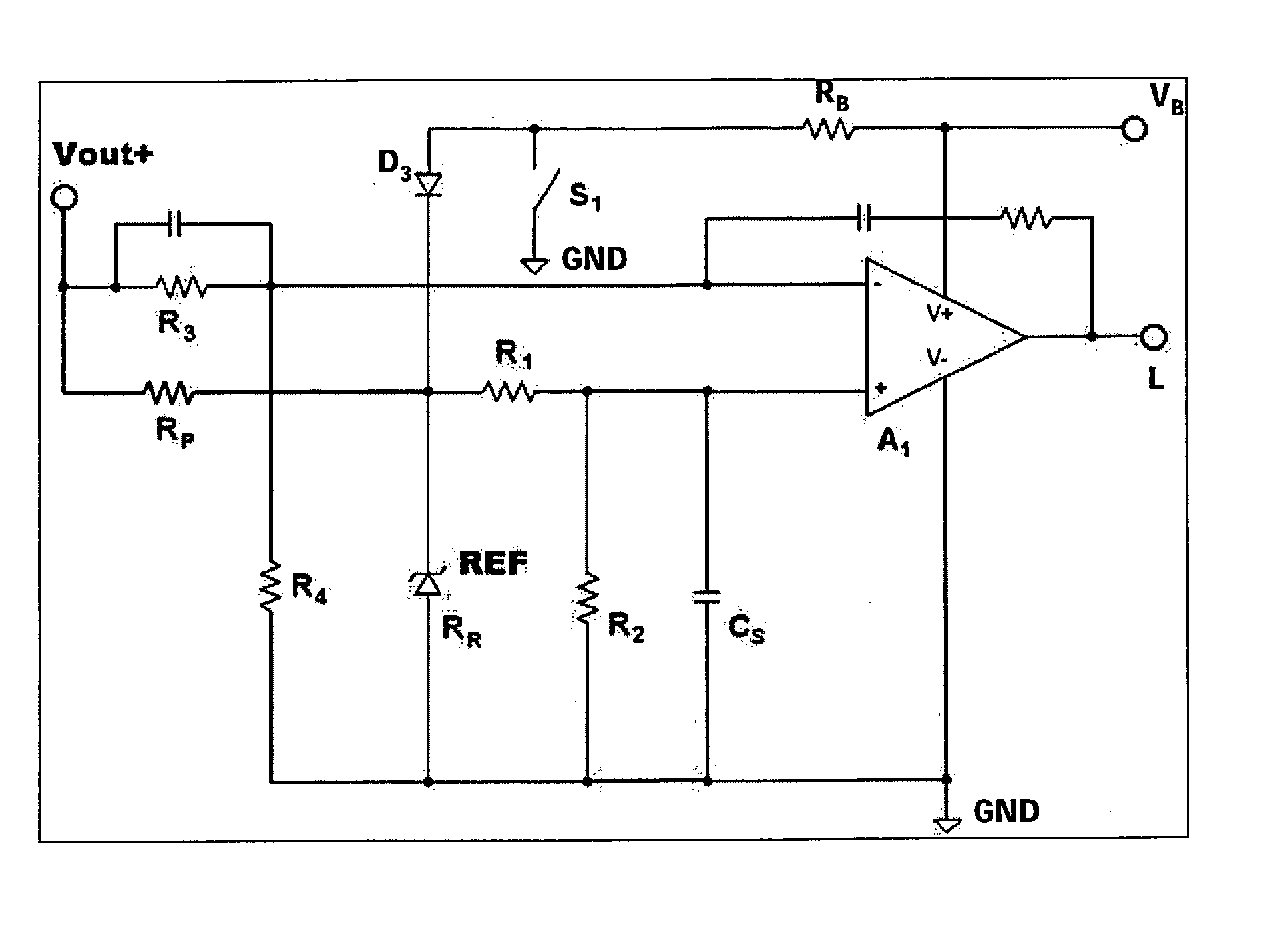
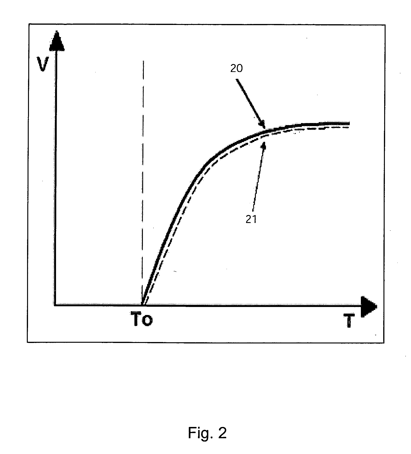
[0060] As shown in FIG. 6, the control circuit is built such that before a turning-on T0 of the switching power supply the controller reference 22 is the slave that follows the bus voltage 23 which is the master. At the moment when the converter is turned on T0, the master / slave relationship changes such that after the turning-on T0 of the switching power supply the output 21 voltage of the switching power supply is the slave that follows the reference 20. Hence, the status of the output level is memorized by the voltage loop prior to start-up of the converter such that the conflict between the soft-starting voltage loop of the co...


PUM


Abstract

In a control circuit for powering up a switching power supply into a powered output bus, the control circuit is built such that before a turning-on of the switching power supply the controller reference is the slave that follows the bus voltage which is the master. At the moment when the converter is turned on, the master / slave relationship changes such that after the turning-on of the switching power supply the output voltage of the switching power supply is the slave that follows the controller reference. Hence, the status of the output level is memorized by the voltage loop prior to start-up of the converter such that the conflict between the soft-starting voltage loop of the converter and the pre-biased output is minimized.

Description

CROSS REFERENCE T0 RELATED APPLICATIONS [0001] This application claims priority from provisional patent application Ser. No. 60 / 557,097 filed Mar. 26, 2004 in the name of Bogdan T. Bucheru entitled “Method and Circuits for Powering Up A Switching Power Supply Into A Powered Output Bus” incorporated herein by reference.TECHNICAL FIELD [0002] The invention relates to a control circuit and a method for controlling a switching power supply, the control circuit including a controller for controlling a switching of the switching power supply. The invention further relates to a switching power supply and an arrangement of at least two switching power supplies with such a control circuit. BACKGROUND ART [0003] One way of decreasing power consumption is to use lower supply voltage and this method is now often used for the new generations of microprocessors. Non-isolated voltage regulation modules (VRM) or isolated DC-DC converters must deliver now much more current and must sustain very high...

Claims


Application Information

Patent Timeline
IPC IPC(8): G05F1/40H02M1/08H02M1/36H02M3/00
CPCH02M1/36H02M2001/0025H02M3/285H02M3/1584H02M1/0025
Inventor BUCHERU, BOGDAN T.
Owner DET INT HLDG LTD
Why Eureka
Try Eureka