
Methods of heating energy storage devices that power downhole tools

Active Publication Date: 2005-09-29
HALLIBURTON ENERGY SERVICES INC
View PDF19 Cites 61 Cited by
  • Summary
  • Abstract
  • Description
  • Claims
  • Application Information

AI Technical Summary

Benefits of technology

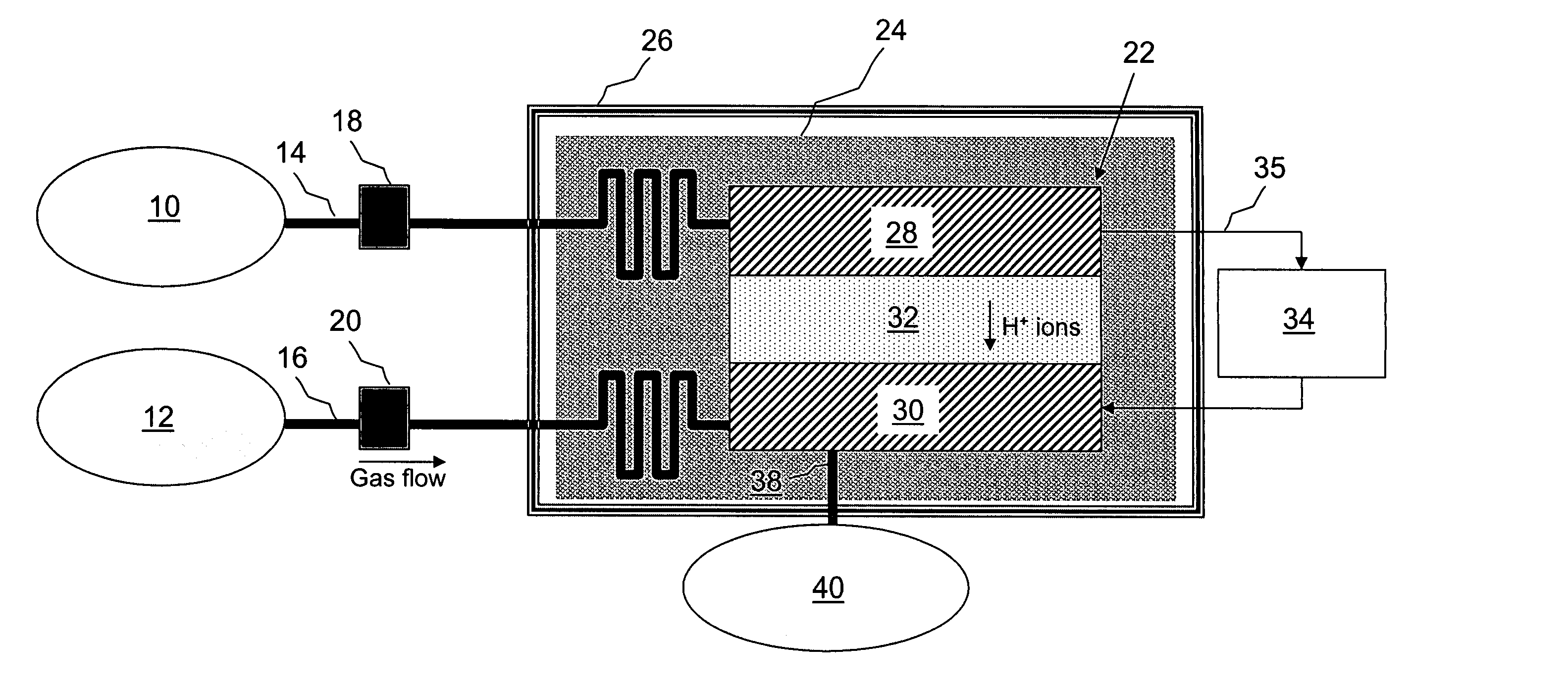
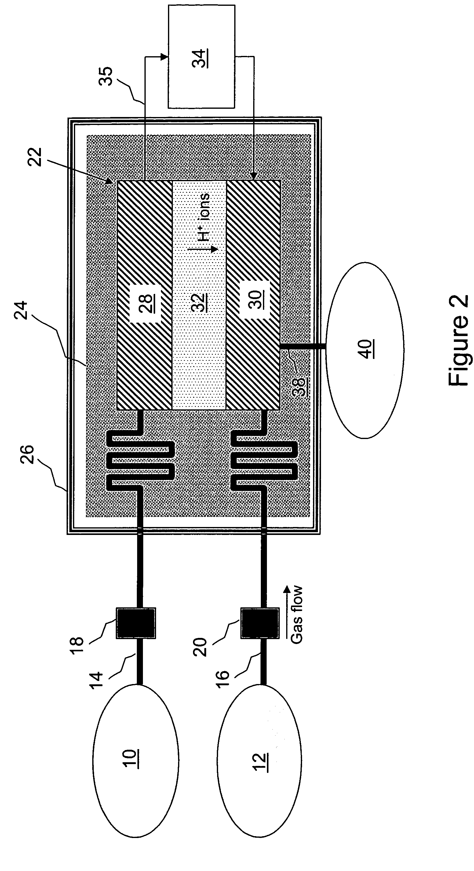
[0005] Methods of preparing an energy storage device for powering a downhole tool include heating an energy storage device to an effective temperature to improve the operability of the energy storage device. The energy storage device may comprise, for example, a primary battery, a secondary battery, a fuel cell, a capacitor, or combinations thereof. The effective temperature to which the energy storage device is heated is usually greater than an ambient temperature in the wellbore near the energy storage device. The energy storage device may be heated using various heat sources such as an ohmic resistive heater, a heat pump, an exothermic reaction, a power generator, a heat transfer medium, the energy storage device itself, a downhole tool, or combinations thereof. A thermal conductor may extend between the heat source and the energy storage device. Further, a thermal insulator and / or an electrical insulator may at least partially surround the heat source and the energy storage device. In an embodiment, the energy storage device is a fuel cell, and the reactants being fed to the fuel cell are pre-heated via heat exchange with the fuel cell itself.

Problems solved by technology

However, power generators are relatively complex and often malfunction, resulting in the inability to use downwhole tools powered by such generators until the generators have been repaired or replaced.
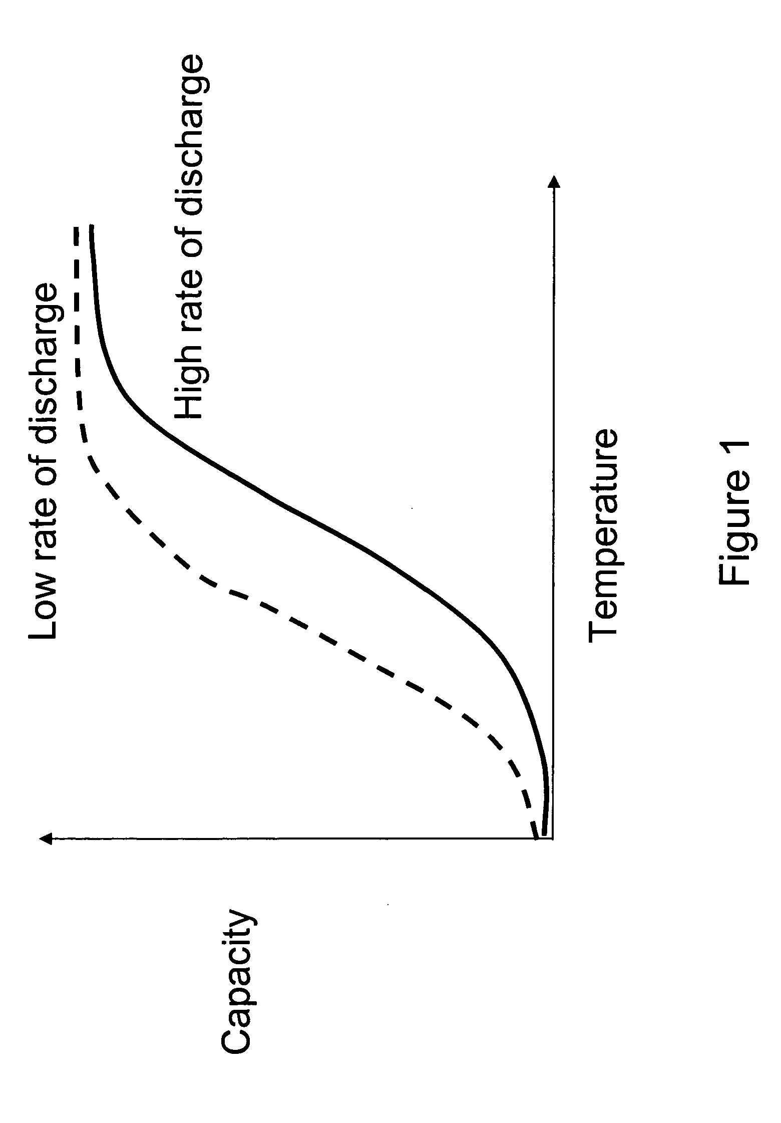
Unfortunately, ambient temperatures in the wellbore are often lower than the minimum operating temperatures of energy storage devices utilized therein.
As a result, those devices fail to provide downhole tools with sufficient power to operate at full capacity.
This problem is commonly encountered when an energy storage device is used at shallow depths in a wellbore where downhole temperatures are lowest.

Method used


Image

  • Methods of heating energy storage devices that power downhole tools
  • Methods of heating energy storage devices that power downhole tools
  • Methods of heating energy storage devices that power downhole tools

Examples


Embodiment Construction

[0015] An energy storage device for powering a downhole tool may be heated to an effective temperature to improve the operability of the device. As used herein, “energy storage device” refers to a device having the ability to store energy that can be used to power a downhole tool, wherein the energy storage device may be located in various locations such as downhole, in an oilfield conduit such as a subsea riser or service tubing / string, or at the surface, and wherein it is not necessarily being used to power a downhole tool while it is being heated. Further, as used herein “downhole tool” refers to a device that can be used to prepare for and engage in the recovery of material from a subterranean formation, wherein the downhole tool is not limited to downhole operation. For example, it may be operated at the surface for testing purposes. Examples of downhole tools that may be operably connected to the energy storage device include a wellbore completion tool, a sensor, a data storag...


PUM


Abstract

An energy storage device for powering a downhole tool may be heated to an effective temperature to improve the operability of the energy storage device. The energy storage device may comprise, for example, a primary battery, a secondary battery, a fuel cell, a capacitor, or combinations thereof. The effective temperature to which the energy storage device is heated may be greater than an ambient temperature in the wellbore near the energy storage device. The energy storage device may be heated using various heat sources such as an ohmic resistive heater, a heat pump, an exothermic reaction, a power generator, a heat transfer medium, the energy storage device itself, a downhole tool, or combinations thereof. A thermal conductor may extend between the heat source and the energy storage device. Further, a thermal insulator may at least partially surround the heat source and the energy storage device.

Description

FIELD OF THE INVENTION [0001] The present invention generally relates to the production of subterranean deposits of natural resources, and more particularly to methods of heating energy storage devices located downhole for powering downhole tools. BACKGROUND OF THE INVENTION [0002] Subterranean deposits of natural resources such as gas, water, and crude oil are commonly recovered by drilling wellbores to tap subterranean formations or zones containing such deposits. Various tools are employed in drilling and preparing wellbores for the recovery of material therefrom such as logging tools having sensors for measuring various parameters downhole, data storage devices, flow control devices such as valves, transmitters, and receivers. Electrical power is generally required to power such downhole tools. The electrical power may be generated downhole with a power generator such as a turbine generator. However, power generators are relatively complex and often malfunction, resulting in the...

Claims


Application Information

Patent Timeline
IPC IPC(8): E21B36/00E21B41/00E21B43/24
CPCE21B41/0085E21B36/00
Inventor FRIPP, MICHAEL L.STORM, BRUCE H. JR.HUH, MICHAELSCHULTZ, ROGER LYNN
Owner HALLIBURTON ENERGY SERVICES INC
Learn More