
Bipolar coagulation electrode

a coagulation electrode and bipolar technology, applied in the field of bipolar coagulation electrodes, can solve the problems of unnecessarily large damage to surrounding tissue, complicated structures, high cost, etc., and achieve the effects of simple handling, easy introduction into the operating site, and convenient movemen

Inactive Publication Date: 2005-09-22
SUTTER MEDIZINTECHN
View PDF1 Cites 15 Cited by
  • Summary
  • Abstract
  • Description
  • Claims
  • Application Information

AI Technical Summary

Benefits of technology

[0005] To solve this problem, in accordance with the invention at least one of the two electrode poles is configured so that it is electrically conductive and able to deliver current over only a portion of its circumference and the remaining portion of its circumference is electrically insulated. Therefore, the high-frequency current can be delivered only to one side even with a coagulation electrode without special curvature or bending or angulation of its distal end, so that the tissue on the insulated side of the coagulation electrode facing away from the electrode pole is not damaged and simultaneously the treatment area can be reached better and more selectively by the current. Here, the coagulation electrode according to the invention can be handled just as easily as known unbent coagulation electrodes with circumferential electrode poles. In addition, the power loss in a conductive medium is less for the side limited application, because the energy is transmitted only at this point or applied to the tissue where it is necessary.
[0007] In an alternative, preferred embodiment, the surface of the first electrode pole and the surface of the second electrode pole spaced at a distance from the first electrode pole and from the distal end of the coagulation electrode are configured to be electrically conductive and to deliver power over only a portion of their circumference, the electrically conductive surfaces of the electrode poles delivering power are approximately flush with each other in the longitudinal direction of the coagulation electrode, and the electrically conductive surfaces of the two electrode poles delivering power are approximately the same size. Therefore, the coagulation electrode is active on only one side of its entire longitudinal profile and thus can be particularly gentle on the tissue not to be treated. The current density is also approximately the same size at both electrode poles due to their approximately equal size, which enables uniform application of energy with both electrode poles.
[0008] Therefore it is advantageous when the first and / or the second electrode pole is built to be electrically conductive and to deliver power over approximately one-fourth up to three-fourths, especially over approximately a half, of its circumference. In this way, on one hand the energy can be sufficiently concentrated in the areas to be treated and on the other hand the surrounding tissue is protected by the insulated circumferential areas of the coagulation electrode.
[0010] It is advantageous when the surfaces of the electrode poles are cylindrical and / or curved like a sphere at least in certain regions. Through such a uniform curving, a smooth surface is produced, which makes the coagulation electrode easy to move, especially within the operating site, without damaging tissue. In addition, such outer curvatures can create a large surface area of the electrode poles and if necessary the coagulation electrodes can be easily pressed into the tissue with the curvature, so that the entire electrode pole area can be used to deliver energy.
[0011] For simple handling, it is especially advantageous if the coagulation electrode body holding the electrode poles is formed essentially of flexible material. In this way, the coagulation electrode according to the invention can be easily introduced into the operating site and in general can be moved easily, so that tissue areas that are otherwise hard to reach can also be treated. Advantageously, the electrical connection lines, which are guided in the interior of the coagulation electrode to the electrode poles, can also be flexible. In particular, for use in the working channel of an operating instrument, e.g., an endoscope, a flexible, pliant configuration of the coagulation electrode according to the invention is advantageous.

Problems solved by technology

Through a circumferential application of a high-frequency current, an unnecessarily large amount of surrounding tissue can be damaged, especially during work in tight spaces (e.g., nose, vertebrae, etc.).
Such structures, however, are complicated and expensive.

Method used


Image

  • Bipolar coagulation electrode
  • Bipolar coagulation electrode
  • Bipolar coagulation electrode

Examples


Embodiment Construction

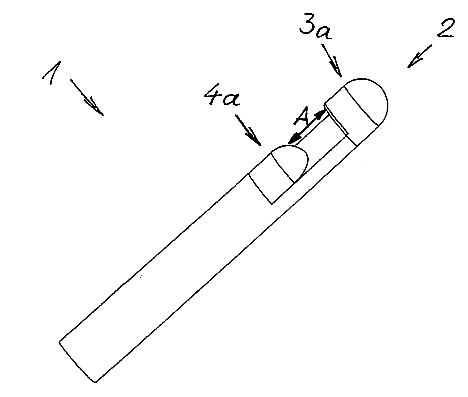
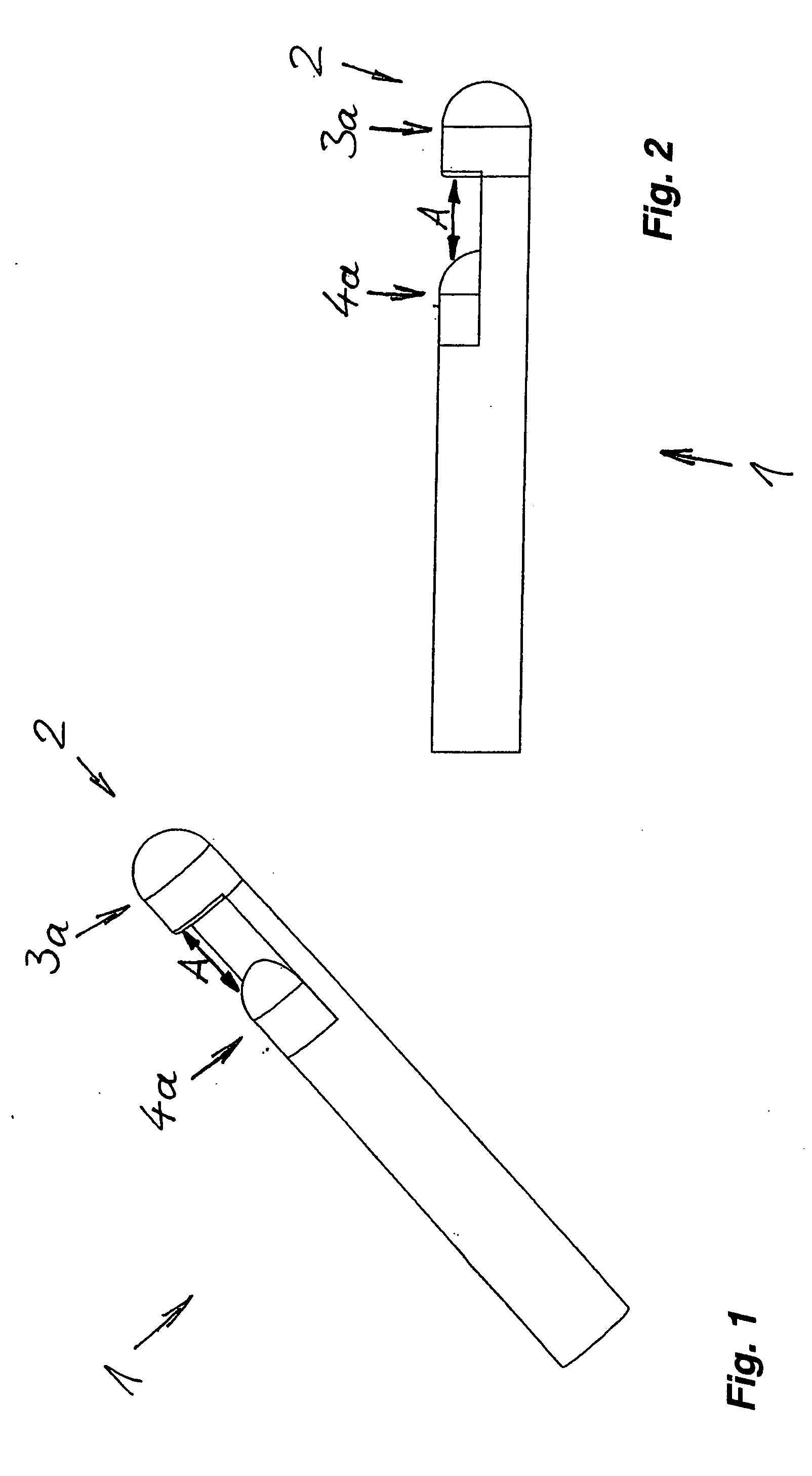
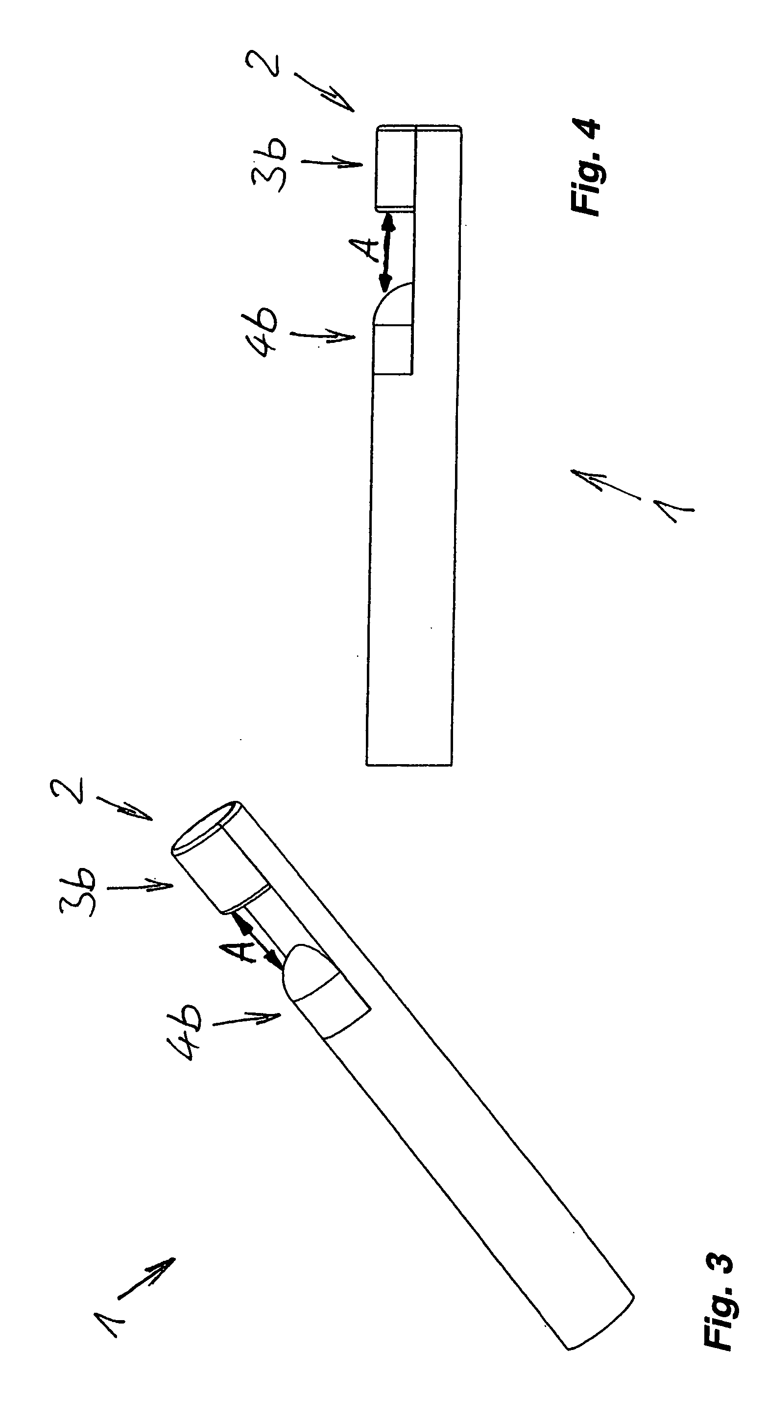
[0017] A bipolar coagulation electrode designated overall with 1 includes two electrode poles arranged at a distance from each other and one behind the other in the region of the distal electrode end 2 in the longitudinal profile of the coagulation electrode 1. In the embodiments shown in FIGS. 1-4, the coagulation electrode 1 is in the unbent position, i.e., in its original, not-in-use position configured essentially in a straight line, wherein the two electrode poles are arranged in a line one behind the other in the direction of the longitudinal axis of the coagulation electrode 1.

[0018] In the embodiment shown in FIGS. 1 and 2, the surface of the first electrode pole 3a arranged at the distal end 2 of the coagulation electrode 1 is formed bare and electrically conductive in the circumferential direction and the second electrode pole 4a at a distance from the distal end 2 is electrically insulated over a portion of its circumference. The first electrode pole 3a is here shaped pa...


PUM


Abstract

A bipolar coagulation electrode (1) has electrode poles (3a, 3b, 4a, 4b) arranged at a distance from each other and one behind the other in a region of the distal electrode end (2) in the longitudinal profile of the coagulation electrode (1). At least one of the two electrode poles (3a, 3b, 4a, 4b) is built to be electrically conductive and to deliver power over only a portion of its circumference and the remaining portion of its circumference is electrically insulated.

Description

BACKGROUND [0001] The invention relates to a bipolar coagulation electrode with two electrode poles arranged at a distance from each other and one behind the other in the region of the distal electrode end in the longitudinal profile of the coagulation electrode. [0002] Such coagulation electrodes are already known and are used during surgical operations to apply bipolar, high-frequency current in order to coagulate biological tissue or for ablation of biological tissue. Coagulation electrodes are also occasionally used within a conductive medium, such as a saline solution. The known coagulation electrodes feature electrode poles at their distal end, which are arranged in the circumferential direction, i.e., which deliver current flowing in the circumferential direction, which are electrically conductive, and which are formed, e.g., as two electrically insulated coaxial elements or as two quarters of a ball at the tip of the coagulation electrode. [0003] Through a circumferential ap...

Claims


Application Information

Patent Timeline
IPC IPC(8): A61B18/14
CPCA61B18/14A61B2018/1497A61B2018/126A61B2018/00083
Inventor SUTTER, BERT H.
Owner SUTTER MEDIZINTECHN
Learn More