
System and method of estimating joint loads in a three-dimensional system

Active Publication Date: 2005-09-22
HONDA MOTOR CO LTD
View PDF65 Cites 49 Cited by
  • Summary
  • Abstract
  • Description
  • Claims
  • Application Information

AI Technical Summary

Benefits of technology

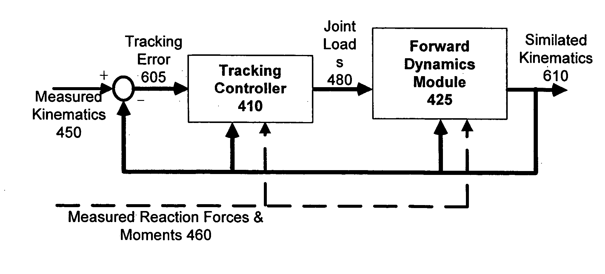
[0014] According to one embodiment, modified acceleration may be computed by using one or more error values representing differences between measured kinematic data and previously simulated kinematic data. A feedback gain is applied to force the error values to zero. Therefore, an advantage of the present invention is that the modified acceleration is computed without the need for calculating higher order derivatives of noisy kinematic data, thereby for allowing for estimation or prediction of joint loads without the errors caused by calculation of higher order derivatives.
[0015] According to further embodiments, the step of estimating a joint load involves recursively estimating the joint loads at successive joints of a three-dimensional system. Recursive embodiments of the present invention are applicable to open chain systems as well as closed chain systems. Therefore, the present invention advantageously eliminates errors caused by parametric uncertainties during estimation of joint forces and moments using closed form, whole body dynamic procedures. According to other embodiments, the step of estimating a joint load involves estimating the joint load using closed form dynamics. Closed form embodiments of the present invention are applicable to open chain systems as well as closed chain systems.

Problems solved by technology

Inverse dynamics analysis is conventionally applied to biomechanics problems because the internal forces of human joints cannot be readily measured.
A big challenge with using inverse dynamics in the study of human motion is the error caused by calculating higher-order derivatives to calculate joint forces and moments.
Experimental observations, however, are imperfect and contaminated by noise.
Sources of noise include the measurement device and the joint itself.
The result of this parabolic noise amplification is erroneous joint force and joint moment calculations.
Although numerical schemes are available to provide estimates of higher order derivatives, the reliability of results is limited since there is no optimal solution or automatic method to filter biomechanical data (Giakas and Baltzopoulos, Optimal Digital Filtering Requires a Different Cut-Off Frequency Strategy for the Determination of the Higher Derivatives, Journal of Biomechanics, 30(8):851-855, 1997, which is incorporated by reference herein in its entirety).
Although techniques exist for filtering the noise, filtering is difficult and time-consuming because much analysis is required to separate the true signal in the biomechanical data from the noise.
A difficulty in low-pass filtering, however, is the selection of an optimal cutoff frequency fc.
Because there is no general solution for selecting optimal filter parameters, filtering techniques often produce unreliable results.
However, the application of optimization-based solutions is limited because convergence and stability are not guaranteed, the methods are computationally expensive, and are generally too complex to implement.
Another problem with using inverse dynamics for analyzing human motion is that the inverse dynamics technique lacks the capability to predict the behavior of novel motions, a problem typically encountered in clinical applications.
An inverse dynamics analysis lacks predictive capability because forces and moments are calculated rather than the expected response from the application of those forces and moments.
Another problem with certain inverse dynamics procedures that utilize only kinematic data is that they utilize whole-body solution.
Parametric uncertainties in an upper body portion, including the physical parameters of the upper body portion or the effects of external loads, are significant sources of error in the estimation of joint forces and moments when using closed form, whole body dynamic procedures.

Method used


Image

  • System and method of estimating joint loads in a three-dimensional system
  • System and method of estimating joint loads in a three-dimensional system
  • System and method of estimating joint loads in a three-dimensional system

Examples


Embodiment Construction

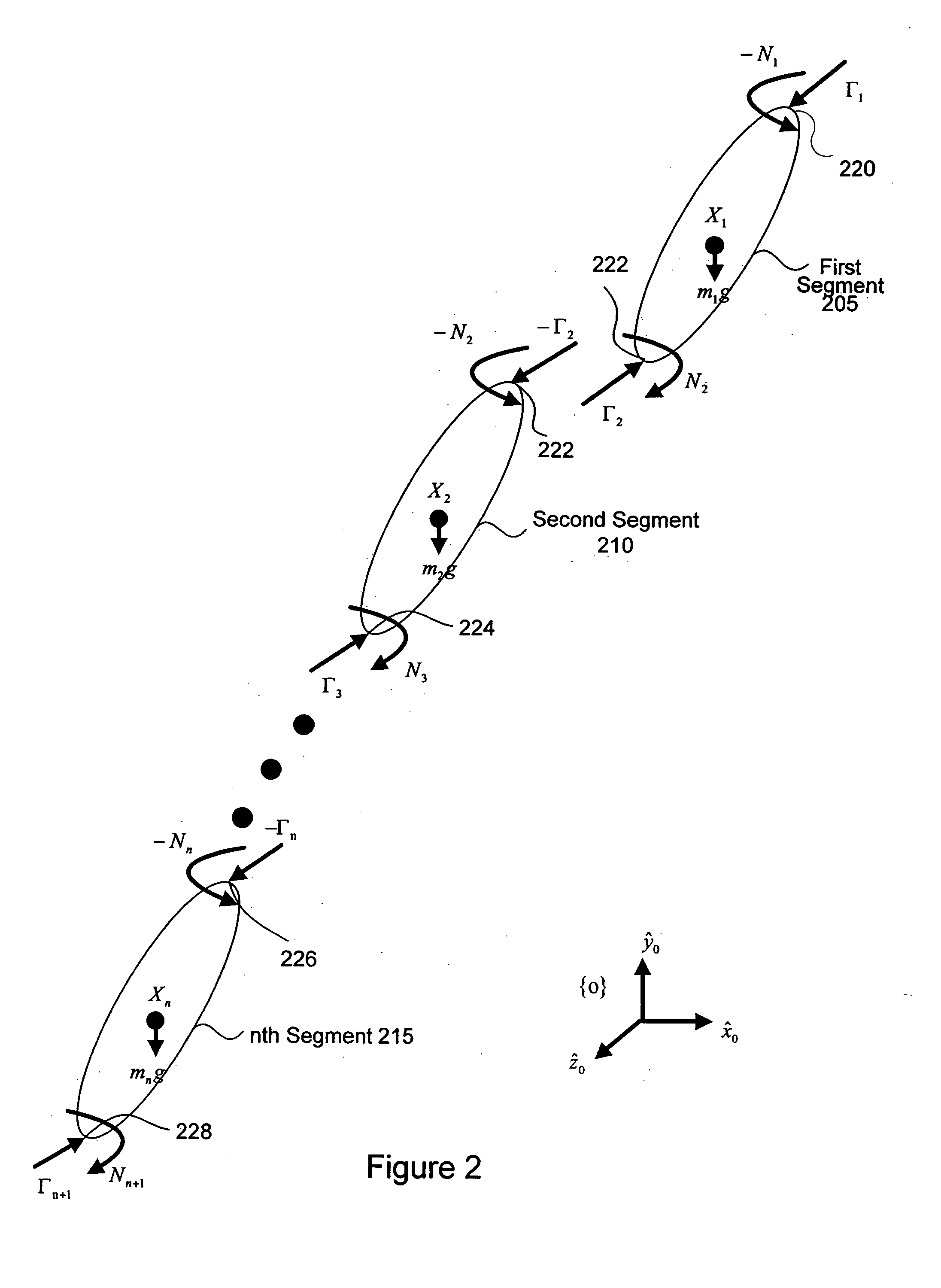
[0031] Various embodiments of the present invention provide for estimation of joint loads in multi-dimensional systems, for example estimation of joint loads in human beings. Various embodiments of the present invention also provide for prediction of motions such as prediction of human motion.

[0032] Various embodiments of the present invention include recursive dynamics, where joint loads are estimated iteratively from one segment to another, as well as closed form dynamics, where all joint loads are computed simultaneously. For example, the selection of a recursive embodiment versus a closed form embodiment may depend upon what sensors are available or on an application for which the invention is being used.

[0033] Embodiments of the present invention include open-chain systems and closed chain systems. In an open chain system, at most one end of the multi-body system is in contact with the environment. The other end or ends are free or unconstrained. In a closed chain system, mor...


PUM


Abstract

A method for estimating joint load at a joint of a segment. The method comprises the steps of receiving kinematic data, determining a modified acceleration using at least the kinematic data, estimating a joint load using at least the modified acceleration; and determining simulated kinematic data for the segment using at least the joint load. The present invention thus addresses the problems with conventional inverse dynamics analysis by providing a forward dynamics solution for estimation of joint loads that is stable, guaranteed to converge, computationally efficient, and does not require acceleration computations. According to one embodiment of the present invention, a joint load is estimated recursively.

Description

CROSS-REFERENCE TO RELATED APPLICATIONS [0001] This application is a continuation-in-part of U.S. patent application Ser. No. 10 / 151,647 filed on May 16, 2002 which claims priority under 35 U.S.C §119(e) from U.S. provisional applications No. 60 / 301,891 filed on Jun. 29, 2001 and No. 60 / 353,378 filed on Jan. 31, 2002 which are all incorporated by reference herein in their entirety. This application is related to U.S. patent application Ser. No. ______, filed on Jan. 19, 2005, entitled “A System and Method of Estimating Joint Loads Using an Approach of Closed Form Dynamics” which is incorporated by reference herein in its entirety. This application is also related to U.S. patent application Ser. No. ______, filed on Jan. 19, 2005, entitled “A System and Method of Predicting Novel Motion in a Serial Chain System” which is incorporated by reference herein in its entirety.FIELD OF THE INVENTION [0002] The present invention relates to human motion analysis and synthesis. The present inve...

Claims


Application Information

Patent Timeline
IPC IPC(8): G06F19/00A61B5/103
CPCA61B5/103A61B5/4528A61B5/1038
Inventor DARIUSH, BEHZAD
Owner HONDA MOTOR CO LTD
Learn More