Magnetic disk drive with feedback control

a magnetic disk drive and feedback control technology, applied in the direction of maintaining head carrier alignment, recording information storage, instruments, etc., can solve the problems of increasing the seek time, deteriorating the transient response of the control system, and difficulty in reaching the target value without errors only with a feedforward inpu

Active Publication Date: 2005-09-22
WESTERN DIGITAL TECH INC
View PDF6 Cites 13 Cited by
  • Summary
  • Abstract
  • Description
  • Claims
  • Application Information

AI Technical Summary

Benefits of technology

[0010] In these well-known examples, the target velocity is derived provided that the target acceleration has been integrated in a continuous time system. The target position is derived provided that the target velocity has been integrated in the continuous time system (the target acceleration has been integrated twice in the continuous time system). However, the head positioning control system in the actual magnetic disk drive is a sampled data control system having a sampler (A / D converter) and a hold (D / A converter). Generally, a zero-order hold for holding the value on a sample point for a sampling time is used for the hold.

Problems solved by technology

Therefore, with the aforementioned methods, it is difficult to reach the target value without errors only with a feedforward input.
Furthermore, these errors are inputted into a feedback controller as tracking errors.
This causes a deterioration of the transient response of the control system and an increase of the seek time.

Method used


Image

  • Magnetic disk drive with feedback control
  • Magnetic disk drive with feedback control
  • Magnetic disk drive with feedback control

Examples


Embodiment Construction

[0025] One embodiment of the present invention is hereinafter described with reference to the drawings.

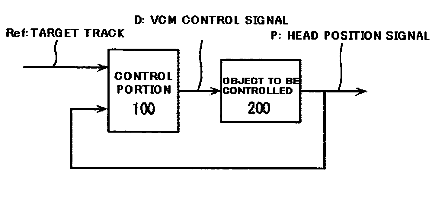
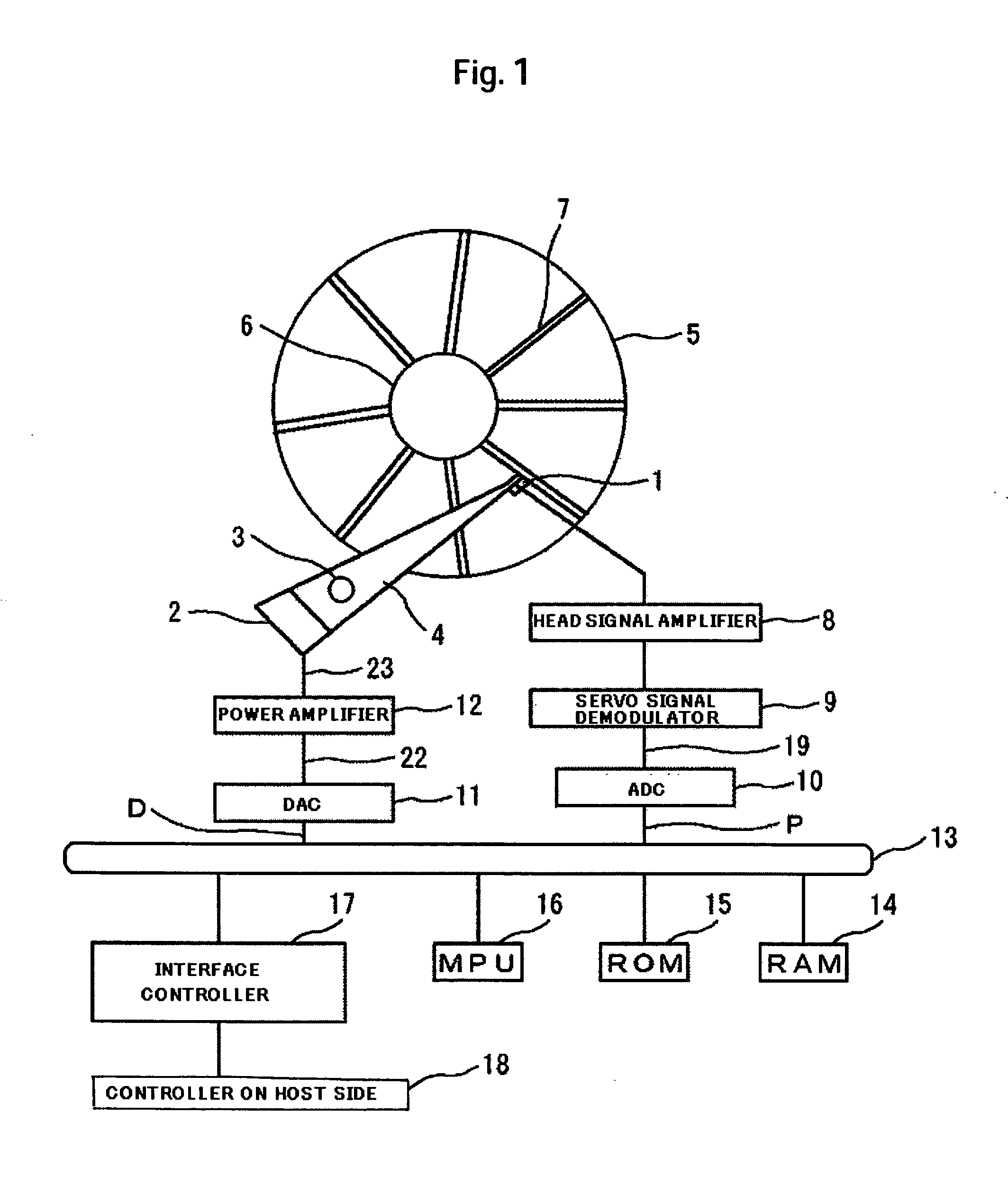
[0026]FIG. 1 is a schematic diagram of the head positioning control system of a magnetic disk drive of one embodiment of the present invention. A magnetic disk 5 that is a recording medium is fixed to a spindle motor 6. It is rotating at a determined rotational speed. Furthermore, a pivot bearing 3 is mounted at a side of the magnetic disk 5 held to the spindle motor 6 and parallel to the axis of the spindle motor. A carriage 4 is swingably fixed to the pivot bearing 3. A magnetic head 1 is fixed to the front end of the carriage 4. Power for moving the magnetic head 1 is produced by a voice coil motor (hereinafter referred to as the VCM) 2. The magnetic head 1 can know the present position by detecting a position signal recorded on a servo sector 7 on the magnetic disk. The position signal detected by the magnetic head is amplified by a head signal amplifier 8 and demodulated by a...


PUM

PropertyMeasurementUnit
distanceaaaaaaaaaa
distanceaaaaaaaaaa
rigid-aaaaaaaaaa

Abstract

A feedforward control system using a polynomial formula not affected by discretization error is realized in a magnetic disk drive. In one embodiment, the magnetic disk drive is intended to move a head for performing at least one of recording and playback to and from a magnetic recording medium to a target position. The feedforward input has a seek control system computed by a polynominal formula of a time function. The coefficients of the polynomial formula have been derived from boundary conditions including the characteristics of a zero-order hold.

Description

CROSS-REFERENCES TO RELATED APPLICATIONS [0001] This application claims priority from Japanese Patent Application No. JP2004-079735, filed Mar. 19, 2004, the entire disclosure of which is incorporated herein by reference. BACKGROUND OF THE INVENTION [0002] The present invention relates to a magnetic disk drive and, more particularly, to a magnetic disk drive adapted to move a magnetic head to a target track. [0003] A magnetic disk drive that is a storage device external to a computer has a magnetic head that moves to a target track on a surface of a rotating magnetic disk to perform recording and playback of data. [0004] Generally, a following control system for causing a magnetic head to keep track of the same track to read and write data, a seek control system for moving the magnetic head to a target track where data is present, and a settling control system for performing a splice from the seek control system to the following control system near the target track are present in a ...

Claims


Application Information

Patent Timeline
Patent Type & Authority Applications(United States)
IPC IPC(8): G11B21/08G05D3/12G11B5/55G11B5/596
CPCG11B5/5547
Inventor ATSUMI, TAKENORI
Owner WESTERN DIGITAL TECH INC
Why Eureka
Try Eureka