
Filtered wringer

Inactive Publication Date: 2005-09-22
CONTINENTAL COMML PRODS
View PDF34 Cites 19 Cited by
  • Summary
  • Abstract
  • Description
  • Claims
  • Application Information

AI Technical Summary

Benefits of technology

[0007] In a preferred embodiment of the present invention as described herein, a wringer comprises an open top and a plurality of side surfaces, with the plurality of side surfaces forming an internal volume. The wringer further comprises a first wringing surface that is movable between a first position and a second position, a second wringing surface having at least one perforation, and a filter that is disposed on the second wringing surface. The internal volume of the wringer body is decreased as the first wringing surface is moved from the first position to the second position, and the filter is configured and adapted to prevent dirt particles or other waste particles from flowing through the at least one perforation during wringing.
[0008] In a second preferred embodiment, a wringer comprises a wringer body having an open top and a plurality of side surfaces, with the plurality of side surfaces forming an internal volume, a first wringing surface movable between a first position and a second position and having at least one perforation, and a filter that is disposed on the first wringing surface. The internal volume of the wringer body is decreased as the first wringing surface is moved from the first position to the second position, and the filter is configured and adapted to prevent dirt particles from flowing through the at least one perforation during wringing.

Problems solved by technology

However, dirt and other contaminants that are picked by the mop during mopping accumulate within the bucket.
Within a relatively short period of time, the cleansing fluid can become too dirty to continue to be used effectively, and will need to be replaced.
In a mopping activity, the amount of time required to complete a task is prolonged because of the need to frequently replace the cleansing fluid used with the mop.
Therefore, there is a need for a device that will allow for the reclamation of cleansing fluid from a mop that has been used while simultaneously removing dirt particles, waste particles and other contaminants from the cleansing fluid, thus prolonging the useful life of the cleansing fluid.

Method used


Image

  • Filtered wringer
  • Filtered wringer
  • Filtered wringer

Examples


Embodiment Construction

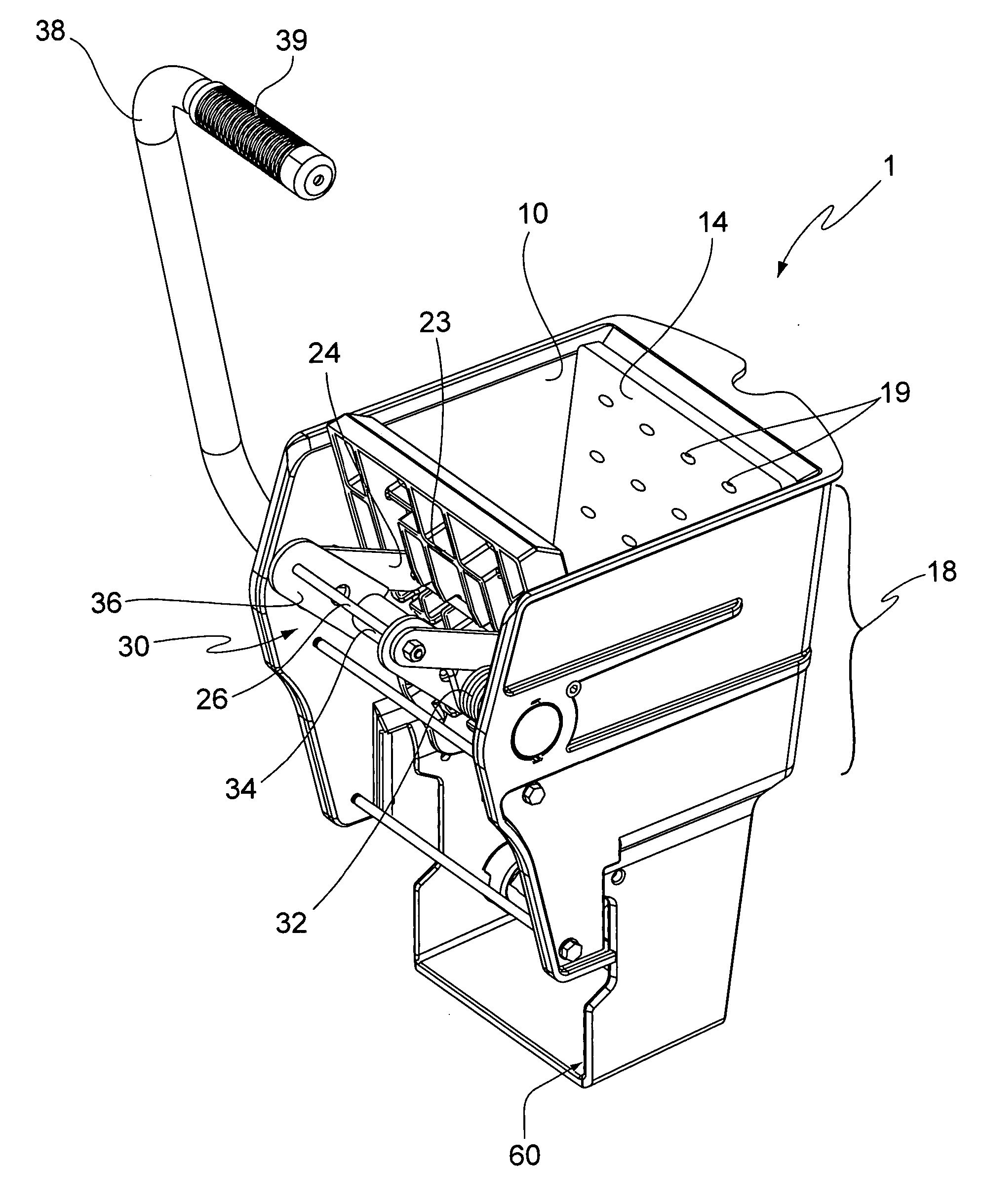
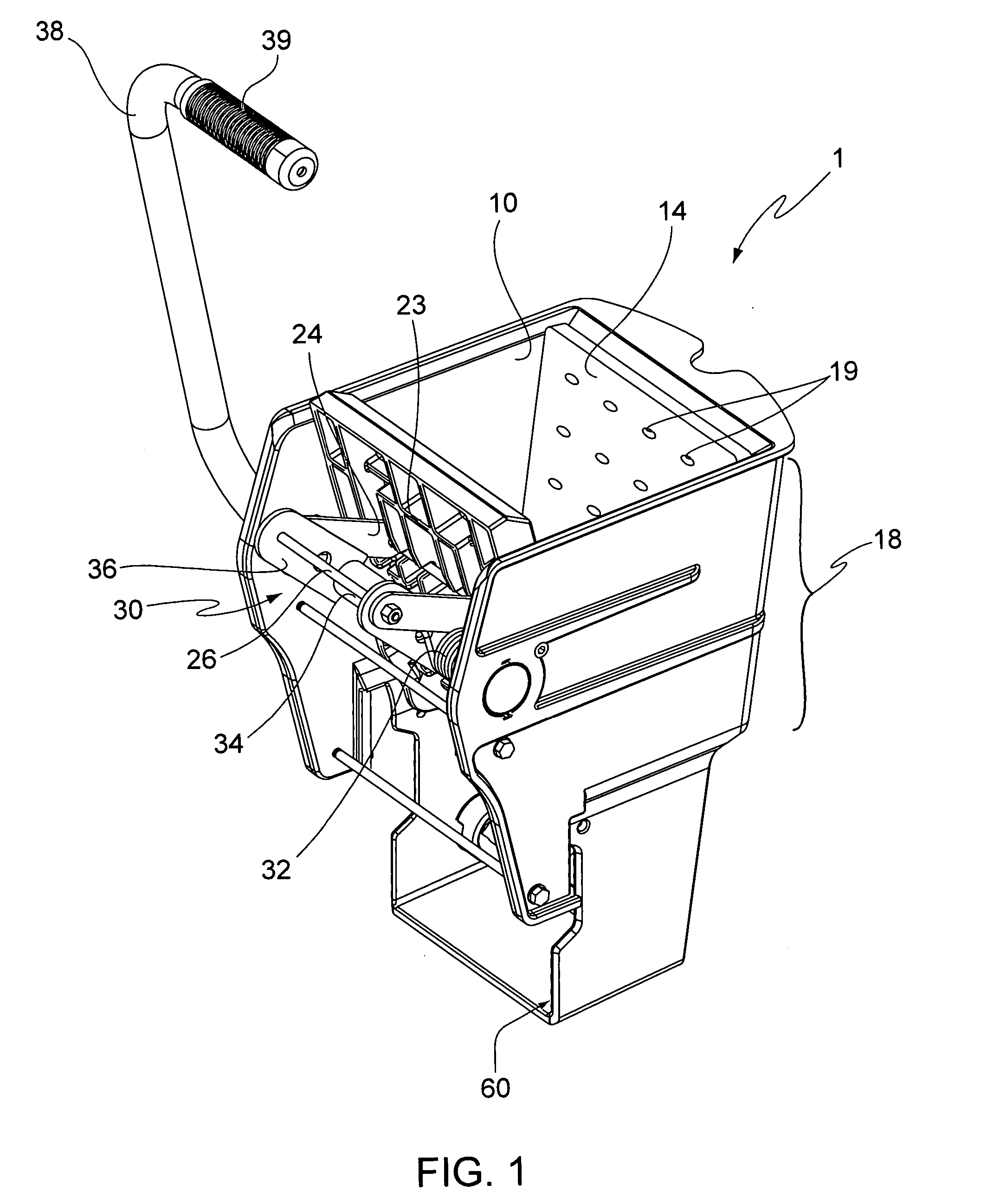
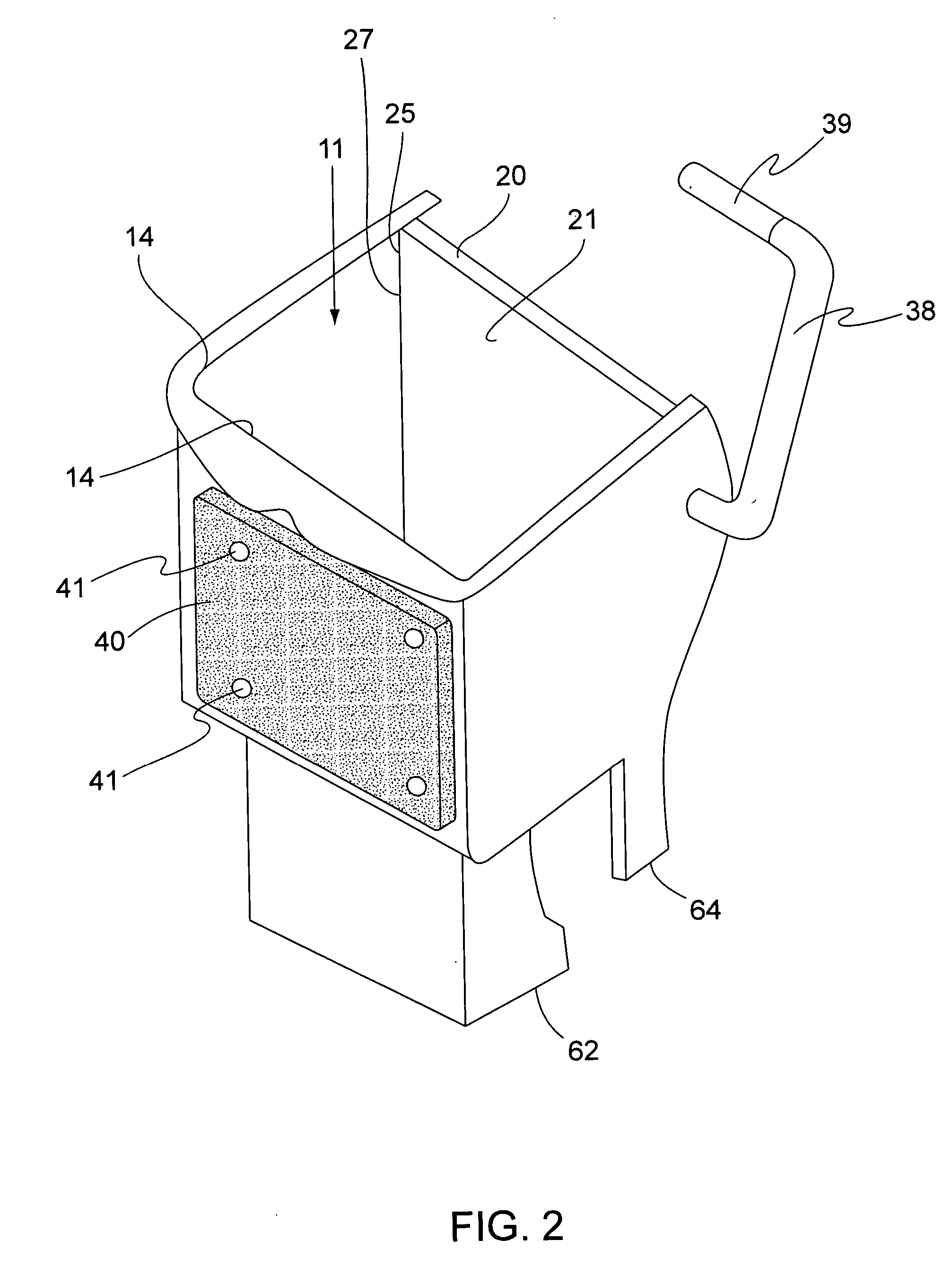
[0024]FIGS. 1-4 illustrate a first preferred embodiment of the present invention as described herewith. Wringer 1 generally comprises container 10, actuator 30, filter 40, and attachment member 60. Container 10 has open top 12, a plurality of side walls 14, movable section 20, and perforated section 18, which define an internal volume 11. Movable section 20 is movable from a first position A to a second position B (see FIGS. 3A and 3B, further described below), which reduces the size of internal volume 11. Sealing members 24 on edges 22 of movable section 20 minimize the leakage of fluid from container 10 where movable section 20 meets side walls 14. However, even if some fluid is able to leak out of container 10 through edges 22, this does not seriously hamper the effectiveness of the present invention. In a preferred embodiment, the components of container 10 are made of plastic, although other materials, such as metal, may also be used.

[0025] Movable section 20 is generally rect...


PUM


Abstract

A wringer for use with wet mops is disclosed. The wringer includes a body having a plurality of side surfaces and at least one perforated section. A filter is disposed adjacent to the perforated section, so that fluid exiting the container through the perforated section will pass through the filter. The filter may be secured to the wringer by slots formed in the wringer body, or with pins, clips or any other similar attaching means. The filter removes dirt and other contaminants from cleansing fluid used with the mop, lengthening the useful lifetime of the cleansing fluid before replacement is needed. The wringer may also have an attachment member to allow the wringer to be used with a bucket or may be formed integrally with a bucket.

Description

FIELD OF THE INVENTION [0001] The present invention relates to wringing devices for use in the floor-maintenance industry. More particularly, the present invention relates to a mop wringer having a filter for prolonging the useful life of a floor care fluid used with mops during floor maintenance, while also reducing the labor associated with such floor maintenance. BACKGROUND OF THE INVENTION [0002] Labor is the largest expense item in cleaning. Innovations which minimize the amount of time required to complete cleaning activities reduce overall costs associated with such necessary maintenance. [0003] In the prior art, a mop is often used with a bucket / wringer combination. The bucket is filled with a cleansing fluid, which is usually a mixture of water and detergent. The mop is inserted into the bucket to rinse it and / or to absorb the cleansing fluid. The wringer is used to remove excess fluid from the mop before it is used to clean a floor or other surface. The fluid from the wrin...

Claims


Application Information

Patent Timeline
IPC IPC(8): A47L13/59
CPCA47L13/59
Inventor BURNS, THOMAS D.
Owner CONTINENTAL COMML PRODS
Learn More