
Ball chain and connector for tessellated patterns

a technology of ball chain and connector, which is applied in the direction of bracelets, wristwatch straps, other domestic articles, etc., can solve the problems of not providing more than two connections, not allowing users to easily modify the existing ball chain connection, and not allowing easy connection and disconnection

Inactive Publication Date: 2005-09-15
BOLAND PAUL E
View PDF14 Cites 9 Cited by
  • Summary
  • Abstract
  • Description
  • Claims
  • Application Information

AI Technical Summary

Benefits of technology

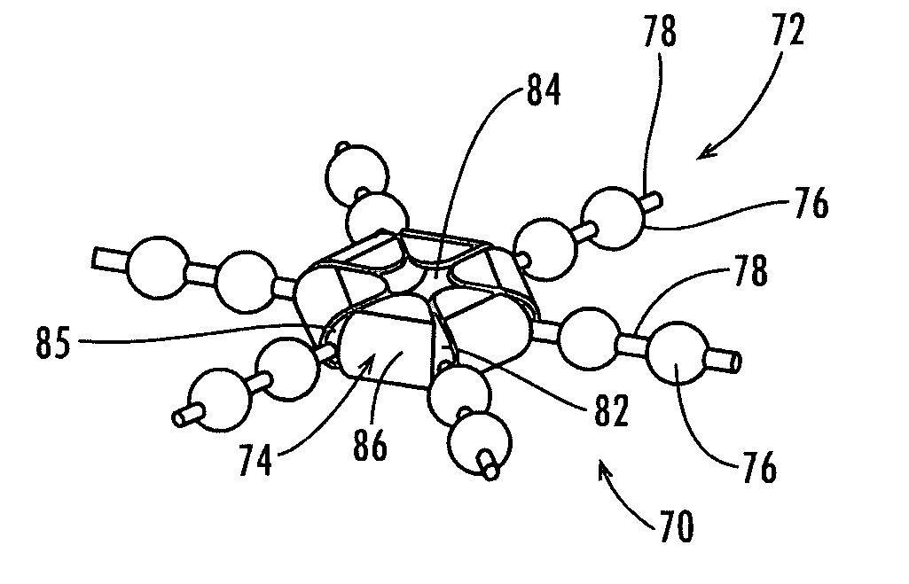
"The present invention is a ball chain assembly with a chain connector that can connect several ends of ball chains. The ball chains have a plurality of balls and links of a breadth less than the breadth of the balls, with the links positioned intermediate adjacent ones of the balls and connecting them in series. The chain connector has a one-piece construction with opposed front and rear surfaces, a center, and a perimeter surface surrounding the center. The chain connector defines an array of ball-receiving sockets and slots for receiving the balls and links of the chains. The chain connector can be made of strong materials like metal or plastic. The device can be formed as a disc, sphere, oval, or other circular shape or as a multi-sided polygon shape. The chain connector can accommodate any size ball chain by scaling the body to accommodate each differently sized terminal ball. The technical effects of this invention include the ability to connect multiple ends of ball chains with a chain connector, and the ability to accommodate different sizes of ball chains."

Problems solved by technology

Although this type of chain connector has been known, it does not provide for more than two connections.
Further, it does not allow a user to easily modify the existing ball chain connections.
17,970, 1,814,710, and 2,557,970, but they are formed of more than one piece of material and / or do not allow for easy connection and disconnection of the chains.
Thus, a heretofore unaddressed need exists in the industry to address the aforementioned deficiencies and inadequacies.

Method used


Image

  • Ball chain and connector for tessellated patterns
  • Ball chain and connector for tessellated patterns
  • Ball chain and connector for tessellated patterns

Examples


Embodiment Construction

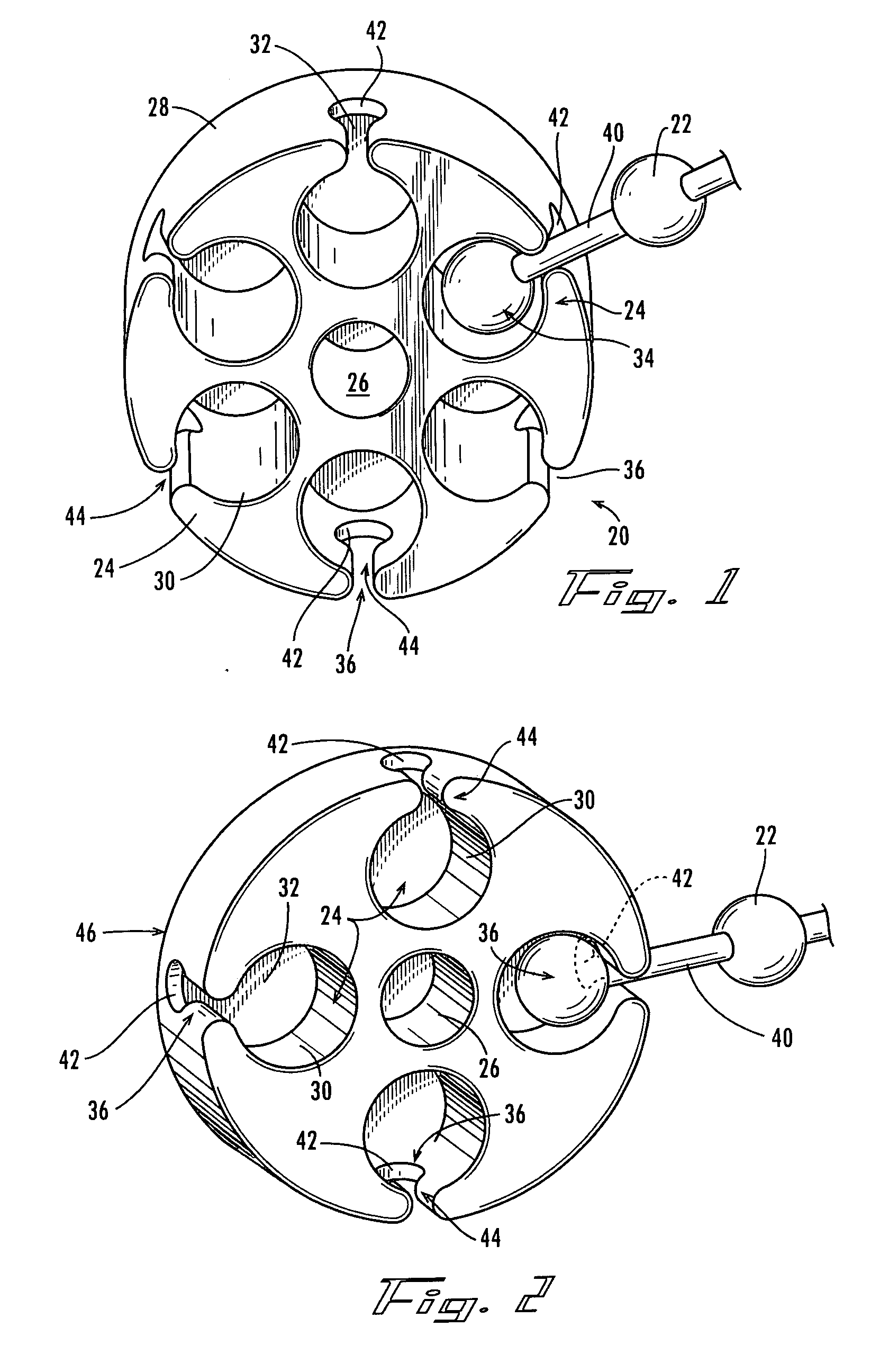
[0031] Referring now in more detail to the drawings, in which like numbers refer to like parts throughout the figures, FIG. 1 shows a one-piece ball chain connector 20 that is a single piece structure configured to receive the terminal ball 34 of up to six ball chains, such as ball chain 22. The chain connector 20 is a one piece molded monolithic structure. The ball chain connector 20 defines an array of ball-receiving sockets 24 surrounding the central aperture 26, with the ball-receiving sockets located at the perimeter surface 28 of the chain connector 20. Each of the ball-receiving sockets are shaped to receive a terminal ball of a ball chain, such as in a substantially cylindrical configuration 30 that merges into a semi-spherical end point or bottom surface 32.

[0032] Also included in ball chain connector 20 are securing mechanisms in the form of slots 36 that extend from each socket 24 to the perimeter surface 28 and allow for insertion of the links 40 extending from the term...


PUM


Abstract

A ball chain assembly may be used to form tessellated patterns of ball chains. The ball chains include a series of balls and intermediate links of a breadth less than the breadth of said balls. A chain connector of one-piece construction defines a circular array of ball-receiving sockets. Each of the sockets are sized to receive a ball of one of said chains. A ball of the chain can be inserted into one of the sockets of the chain connector where a link of the inserted ball passes through the slot extending from the socket, such that a chain can be connected to each of the sockets.

Description

CROSS-REFERENCE TO RELATED APPLICATION [0001] Applicant claims the benefit of copending U.S. provisional patent application entitled “Connector Coupling Configured To Easily Employ More Than Two Ball Chains” filed on Mar. 9, 2004 and accorded Ser. No. 60 / 551,544, which is entirely incorporated herein by reference.FIELD OF THE INVENTION [0002] The present invention relates to a ball chain assembly, particularly to a chain connector configured to connect more than two ball chains. The ball chain includes a series of balls inter-connected by intermediate links, and the chain connector has sockets for receiving the balls of the chains to allow for the formation of patterns by the chains, including tessellated patterns. BACKGROUND OF THE INVENTION [0003] Ball chains are presently used as light weight yet strong chains for holding various objects, particularly keys and other small objects carried together in a purse or pocket. The ball chains are formed by a series of balls inter-connecte...

Claims


Application Information

Patent Timeline
Patent Type & Authority Applications(United States)
IPC IPC(8): A44C25/00A44B99/00
CPCA44B15/00A44C5/107Y10T24/3904A47G29/10A44C13/00Y10T70/8703
Inventor BOLAND, PAUL E.
Owner BOLAND PAUL E
Learn More