
Industrial controller event logging

a technology of event logging and industrial controllers, applied in the field of industrial controllers, can solve the problems of industrial controllers with complex and individualized logic, industrial controllers with unpredictable and uncontrolled messages generated and transmitted by industrial controllers,

Inactive Publication Date: 2005-09-08
PARAGON TECHN SERVICES
View PDF15 Cites 63 Cited by
  • Summary
  • Abstract
  • Description
  • Claims
  • Application Information

AI Technical Summary

Benefits of technology

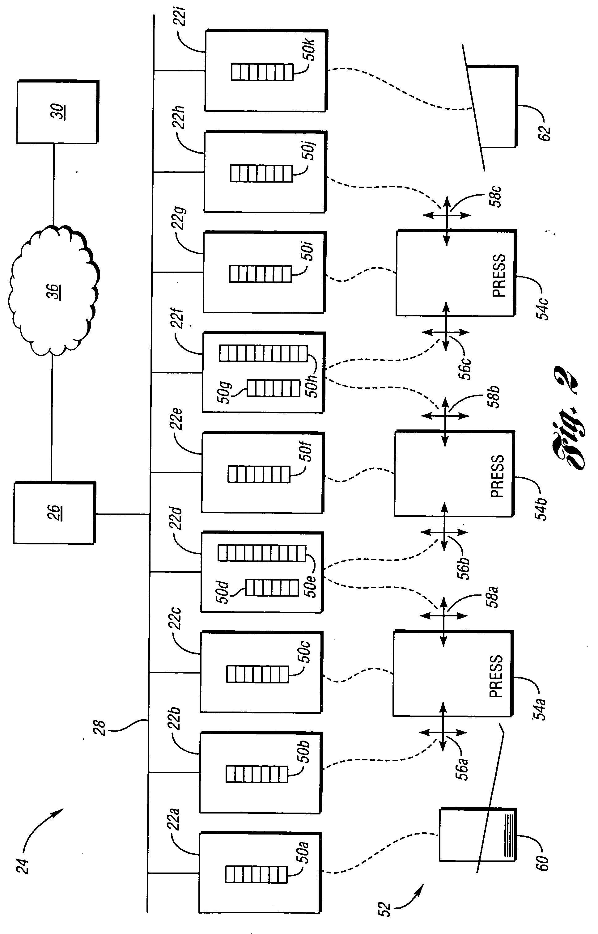
[0017] A method of monitoring industrial equipment is also provided. One of a predetermined set of events is detected in the industrial equipment. An event record is formed by associating the detected event with a time stamp. The event record is pushed onto a finite length queue initiated within an industrial controller. All of the event records held by the queue are read after an interval determined by a scan rate. Any event record matching a previously read event record is discarded as a duplicate event record. The scan rate is dynamically determined based on whether or not any duplicate event records are discarded.
[0018] Another method of monitoring industrial equipment is provided. Event records are pushed onto a finite length queue initiated within an industrial controller. An overflow event is recorded onto the queue if an overflow event is detected. After an interval determined as a scan rate, all event records held by the queue are read and cleared. The scan rate is dynamically determined based on reading at least one overflow event.

Problems solved by technology

Several problems exist with current industrial control monitoring systems.
This typically requires that the industrial controller contain complex and individualized logic for anomaly handling.
A second problem with existing systems results from the unpredictable and uncontrolled nature of messages generated and transmitted by the industrial controllers.
Hence, there is no centralized control of communication network resources.
This may result in wasted network bandwidth and network clogging during critical situations.
Systems that time stamp messages upon receipt at a centralized computer system or when the message is sent from the industrial controller create timing inaccuracies making accurate cause-and-effect analysis difficult.
Fourth, many industrial controllers have limited processing and memory resources.
These limited resources prohibit the implementation of complex network signaling techniques.

Method used


Image

  • Industrial controller event logging
  • Industrial controller event logging
  • Industrial controller event logging

Examples


Embodiment Construction

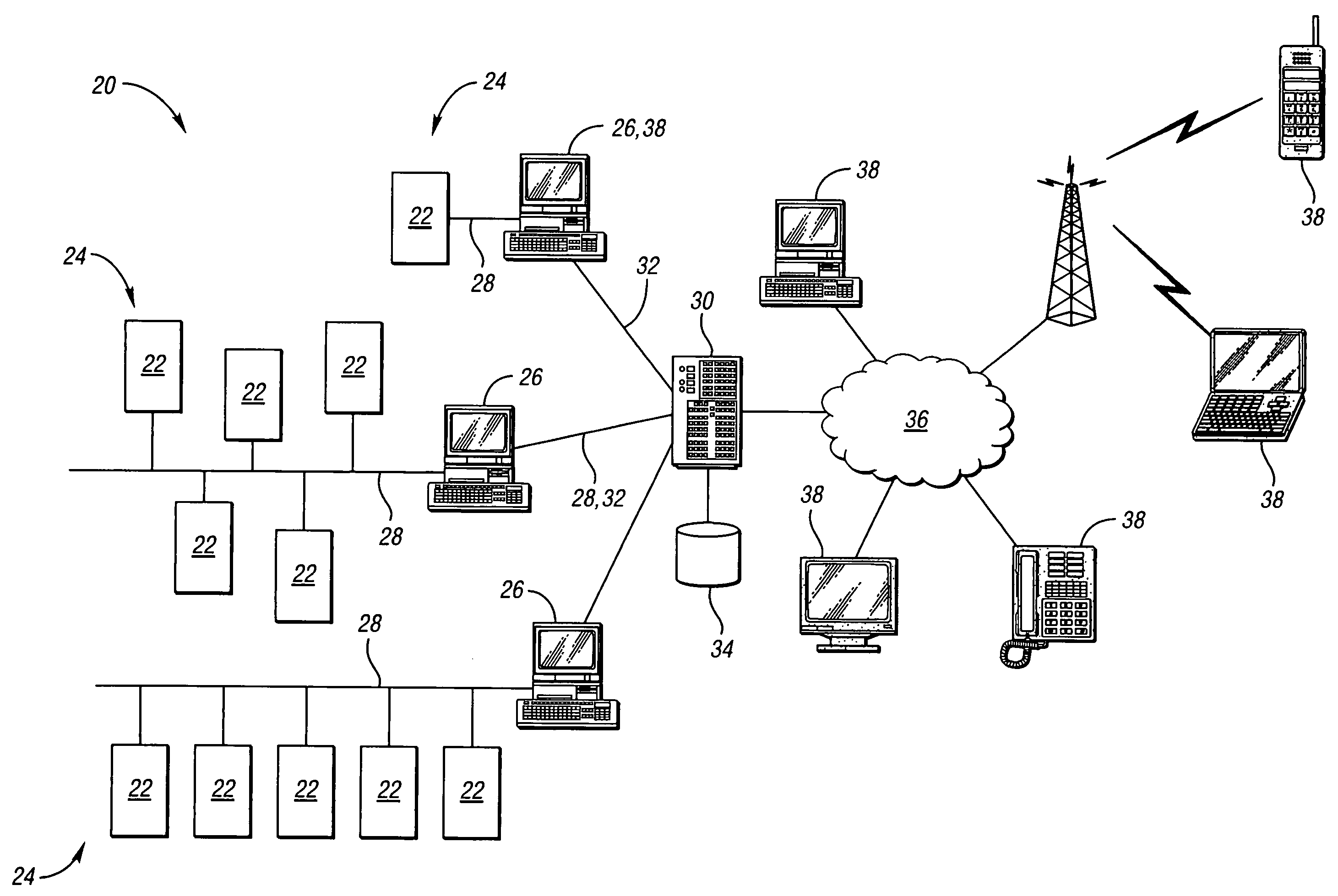
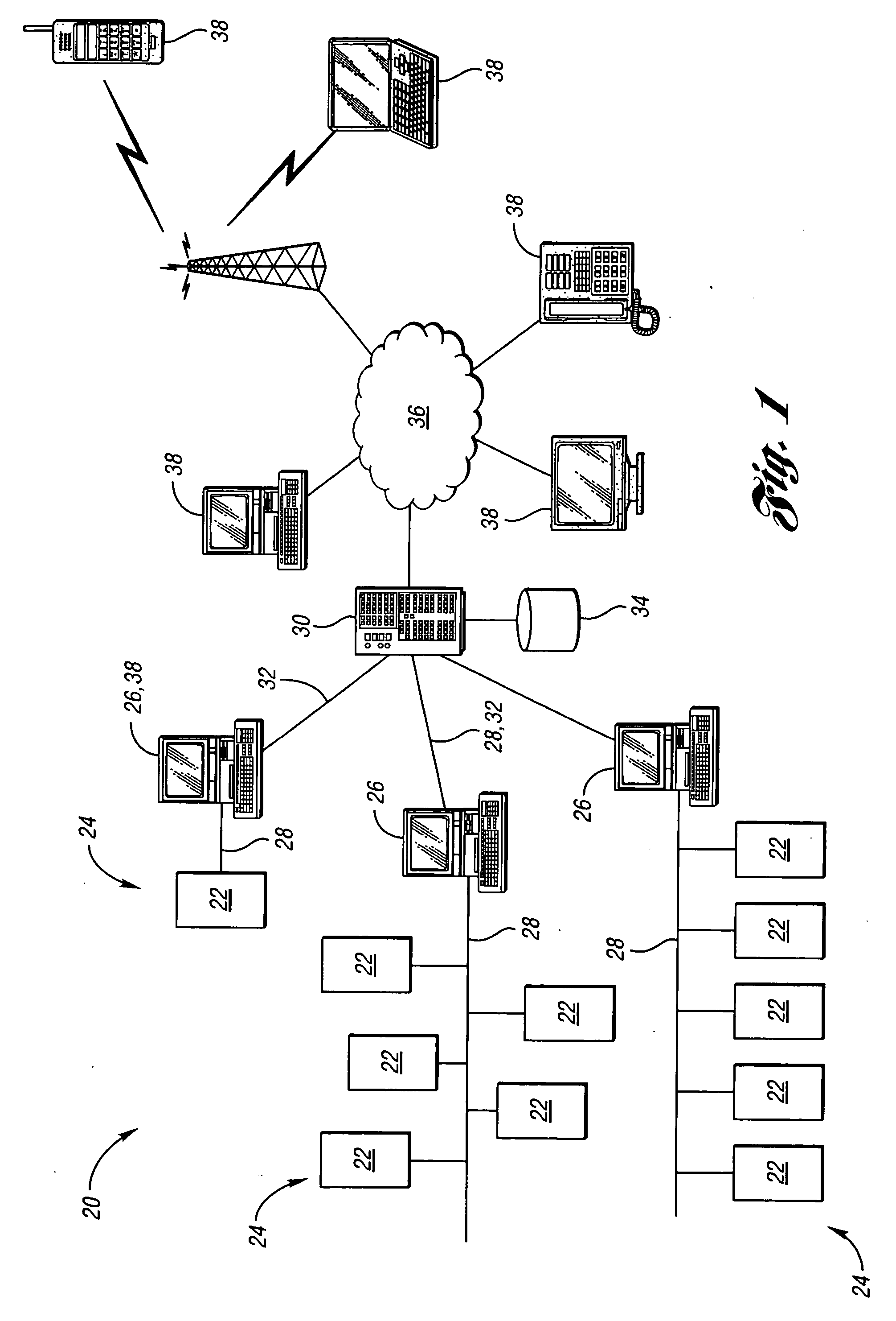
[0027] Referring to FIG. 1, a block diagram illustrating a system for monitoring industrial equipment according to an embodiment of the present invention is shown. A monitoring system, shown generally by 20, includes a plurality of industrial controllers 22. Industrial controller 22 may be any programmable device controlling the operation of industrial equipment. Types of industrial controllers include programmable logic controllers (PLCs), robotic controllers, personal computers, numerical logic controllers, special purpose hardware, dedicated processors, and the like. Industrial controllers 22 establish queues holding event records representing events occurring on monitored equipment.

[0028] Each industrial controller 22 is assigned to one group, shown generally by 24. Each group 24 also include group computer 26. Group computer 26 and industrial controllers 22 within each group 24 are connected through data communication network 28. Data communication network 28 may be any suitab...


PUM


Abstract

Industrial equipment is monitored by at least one industrial controller assigned to each group of industrial equipment. A plurality of queues is established by logic within one of the industrial controllers for each group. Each queue holds a number of event records. Logic is established in each industrial controller for detecting a predetermined event and for storing an indication of the detected event associated with a time stamp as an event record in a queue associated with the predetermined event. A group computer is interconnected with each industrial controller in the group through a data communication network. A scan rate is established for each queue in that group. Event records are periodically read from each queue based on the scan rate for that queue. The event records for all queues in a group are accumulated by the group computer and forwarded to a server. The group computer may dynamically set the scan rate and / or the queue length for each queue based on records read from the queue.

Description

BACKGROUND OF THE INVENTION [0001] 1. Field of the Invention [0002] The present invention relates to the use of industrial controllers for monitoring and reporting the status of industrial equipment. [0003] 2. Background Art [0004] Industrial equipment is used to manufacture or process a wide variety of products, raw materials, intermediate components, and the like. Industrial equipment may also provide a variety of services such as cleaning, packaging, weighing, counting, forming, coating, and the like. Typically, industrial equipment is operated under the control of one or more industrial controllers. Industrial controllers allow the operation of the industrial equipment to be programmed by one or more of the equipment manufacturer, system integrator, plant engineer, and the like. Programmable industrial control can be implemented in special purpose hardware such as robotic controllers, proprietary processors, and the like. Industrial controls may also be implemented in more gener...

Claims


Application Information

Patent Timeline
Patent Type & Authority Applications(United States)
IPC IPC(8): G05B19/00G21C17/00
CPCG05B19/4183G05B19/4185H04L67/12H04L41/069H04L41/0686Y02P90/02
Inventor BOYER, BRADLEY R.
Owner PARAGON TECHN SERVICES
Learn More