Quantitative risk assessment applied to pore pressure prediction

a risk assessment and pore pressure technology, applied in the field of geophysical exploration, can solve the problems of no method discussed above addresses the problem of errors caused, the risk of a catastrophic blowout, and the risk of formation damage, so as to reduce the uncertainty of pore pressure estimation, and avoid well cave-in and formation damage

Active Publication Date: 2005-09-08
GEOMECHANICS INT
View PDF4 Cites 52 Cited by
  • Summary
  • Abstract
  • Description
  • Claims
  • Application Information

AI Technical Summary

Benefits of technology

[0011] One embodiment of the present invention is a method for evaluating a reservoir in a subsurface region of an earth formation. The method uses obtained velocities of the subsurface region from a seismic survey; and estimates from the obtained velocity a formation pore pressure, and an uncertainty associated with the estimated pore pressure. The uncertainty depends at least in part on an uncertainty in the obtained velocity. The formation pore pressure may be estimated using density and effective stress determined from the seismic velocity. Predetermined velocity-density and velocity-effective stress relationships may be used. The uncertainty in pore

Problems solved by technology

If the borehole fluid pressure is significantly below the formation fluid pressure, there is a risk of a catastrophic blowout.
On the other hand, if the borehole pressure is much greater than the formation fluid pressure, the risk of blowout is eliminated but there is risk of formation damage due to fracturing and the mud invading the formation.
None of the methods discussed above address the issue of errors caused by uncertainty in the measurement

Method used


Image

  • Quantitative risk assessment applied to pore pressure prediction
  • Quantitative risk assessment applied to pore pressure prediction
  • Quantitative risk assessment applied to pore pressure prediction

Examples


Embodiment Construction

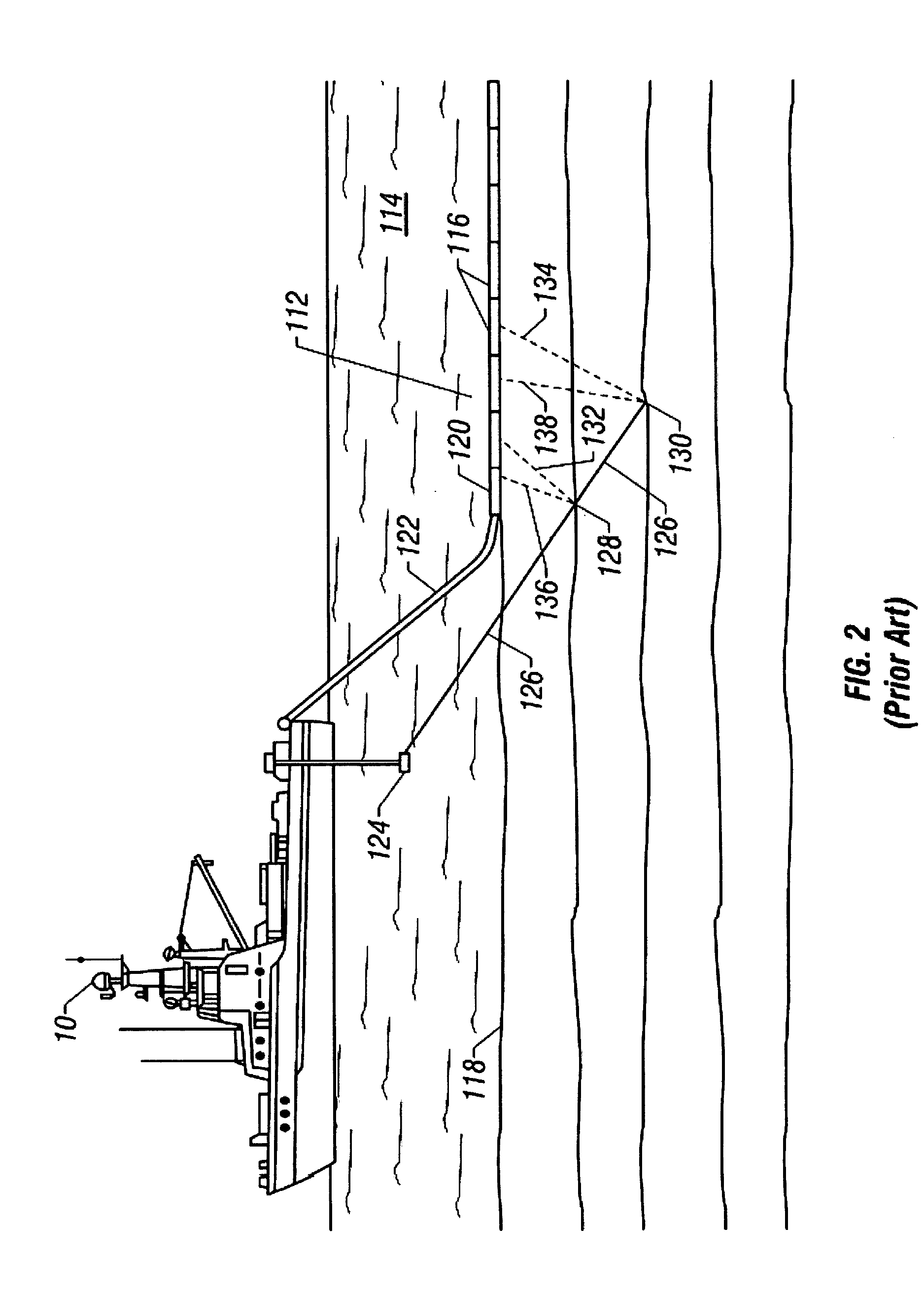
[0032] Referring now to FIG. 1, an example of portions of a marine seismic data acquisition system is illustrated. A vessel 10 on a body of water 15 overlying the earth 16 has deployed behind it a seismic source array 20 and a streamer cable 25. The seismic source array 20 is typically made up of individual air guns 20a, 20b, . . . 20n that are fired under the control a controller (not shown) aboard the vessel 10. Seismic pulses propagate into the earth and are reflected by a reflector 22 therein. For simplifying the illustration, only one reflector is shown: in reality, there would be numerous reflectors, each giving rise to a reflected pulse. After reflection, these pulses travel back to the surface where they are recorded by detectors (hydrophones) 30a, 30b, . . . 30n in the streamer cable. The depth of the source array and the streamer cable are controlled by auxiliary devices (not shown).

[0033] In the seismic data acquisition system of FIG. 1, the sources and receivers are in ...


PUM


Abstract

Pre-drill pore pressure and fracture gradient predictions obtained from seismic velocity data are used in well design taking into account uncertainties in the velocity estimation and in the models that use the velocities to determine pore pressure. Using geological constraints, limits are established on hydrocarbon column height. It is also possible to predict the relative number of casings required to reach target reservoirs.

Description

CROSS REFERENCES TO RELATED APPLICATIONS [0001] This applications claims priority from U.S. Provisional Patent Application Ser. No. 60 / 550,708, filed on Mar. 8, 2004.BACKGROUND OF THE INVENTION [0002] 1. Field of the Invention [0003] The present invention relates generally to geophysical exploration and more particularly to methods for accurately estimating uncertainties in pore pressure and fracture gradient estimation prior to drilling of a well. [0004] 2. Description of the Related Art [0005] Drilling of wells is carried out using a bottomhole assembly that includes a drillbit. During the drilling process, drilling fluid, also referred to as drilling mud, is pumped down the borehole to facilitate the drilling process, cool and lubricate the drillbit, and remove drill cuttings to the surface. If the borehole fluid pressure is significantly below the formation fluid pressure, there is a risk of a catastrophic blowout. On the other hand, if the borehole pressure is much greater than...

Claims


Application Information

Patent Timeline
IPC IPC(8): G01V1/28G01V1/50
CPCG01V1/30G01V2210/6248G01V1/50
Inventor MOOS, DANIELPESKA, PAVELWARD, CHRIS
Owner GEOMECHANICS INT
Why Eureka
Try Eureka