
Vane for a headbox in a paper machine

a paper machine and headbox technology, applied in the field of headboxes, can solve the problems of paper production breakage, turbulence generation, flow detachment from the surface, etc., and achieve the effect of convenient connection of the different parts of the headbox

Inactive Publication Date: 2005-09-08
VALMET TECH INC
View PDF3 Cites 2 Cited by
  • Summary
  • Abstract
  • Description
  • Claims
  • Application Information

AI Technical Summary

Benefits of technology

[0011] Another object is to avoid vane-internal stresses and deformations due to different swelling and thermal expansion of the materials used in the vane.
[0012] In addition, the object is to make the connection of the different parts of the vane easier than heretofore irrespective of whether they are made of the same material or different materials.
[0016] In the construction according to the invention, a pivot member composed of several elements is fastened to a vane component in a method which allows a free stressless movement between the components made of different material and at the same time positions the different components of the vane in relation to each other. Achieving the desired vane geometry often requires using two different materials. For the pivot member, less expensive material can be used than for the vane component. A pivot member composed of several elements is notably easier to manufacture than one long pivot member. The invention also enables avoiding a formation of a step on the joint surface between the pivot member and the vane, which would be disadvantageous for the stock flow.

Problems solved by technology

A problem with this construction is a high step between the fastening component and the vane, which easily leads to that the flow detaches from the surface generating turbulence.
Longitudinal holes may become filled with stock, which causes soiling.
When the stock accumulated in the holes detaches, it may lead to formation of holes in the web and breaks in the paper production.
Similar problems are associated with this solution as with the above-described vane.

Method used


Image

  • Vane for a headbox in a paper machine
  • Vane for a headbox in a paper machine
  • Vane for a headbox in a paper machine

Examples


Embodiment Construction

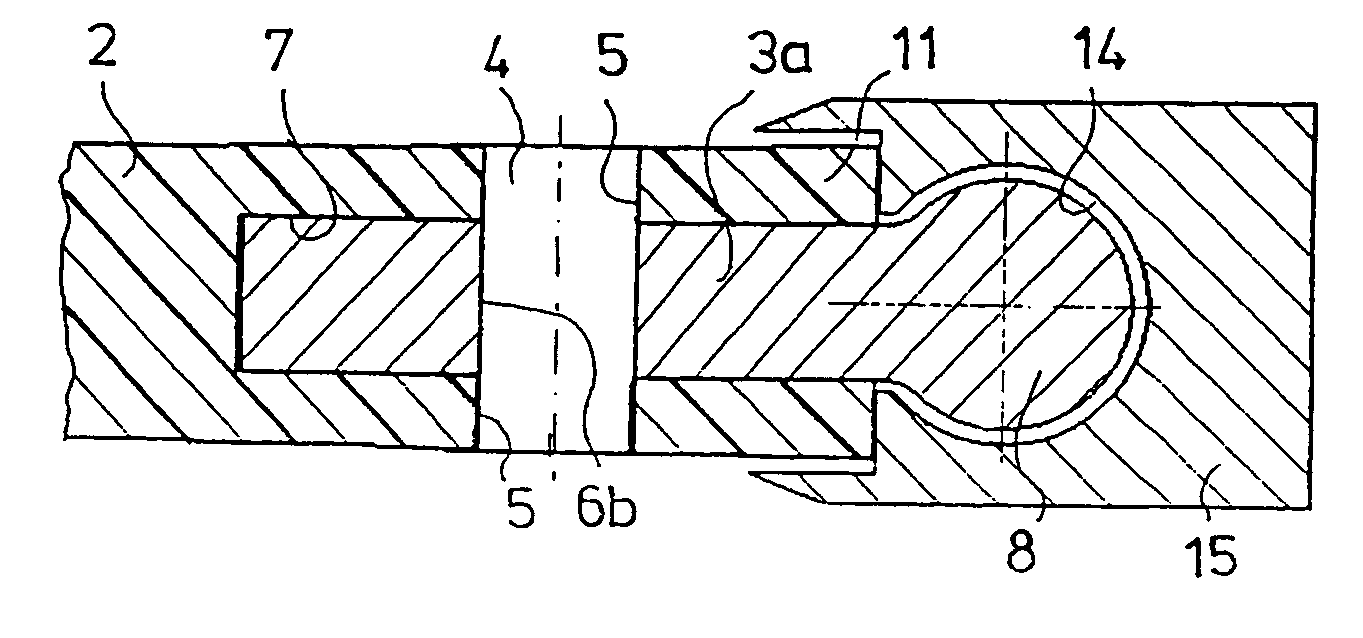
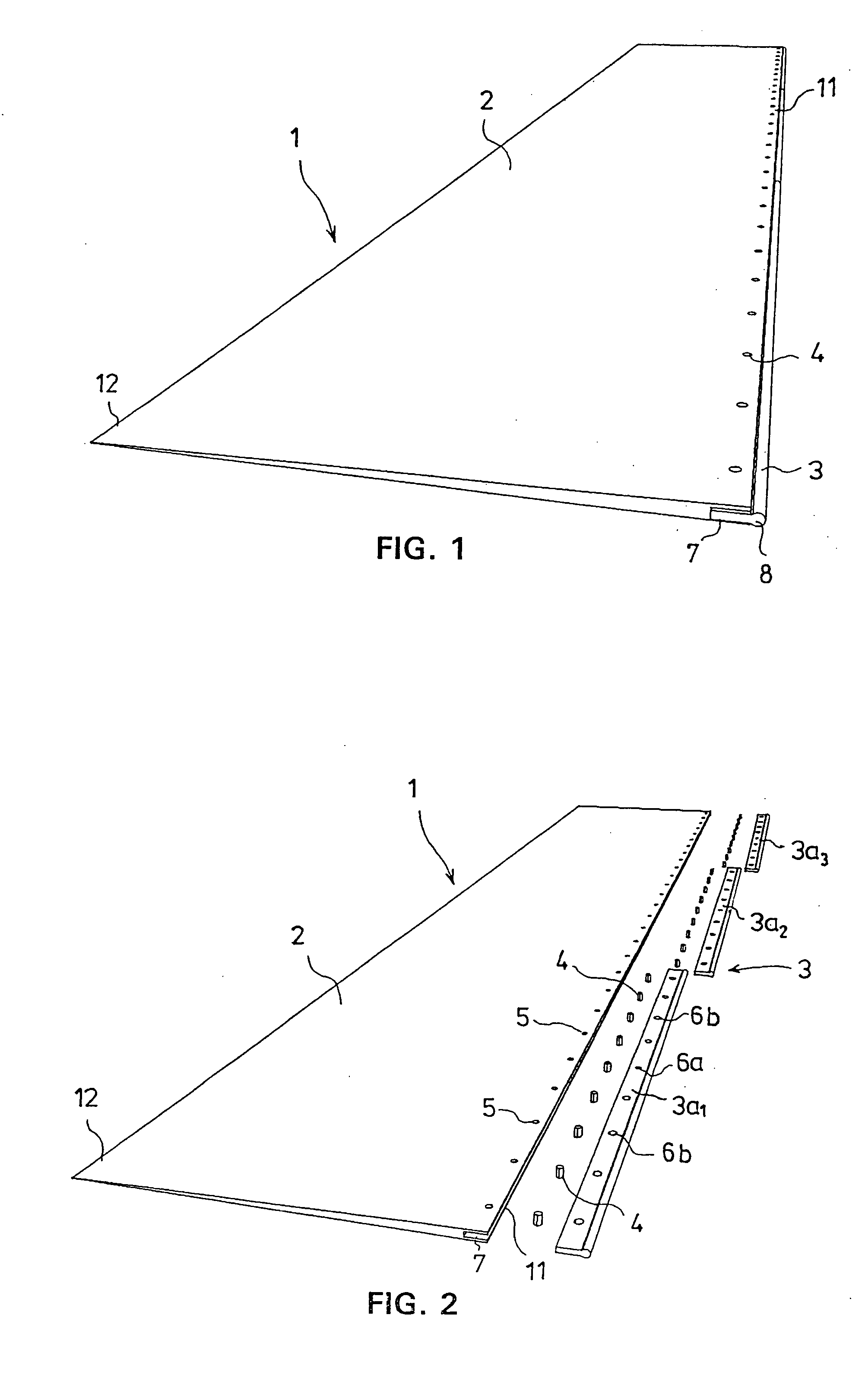
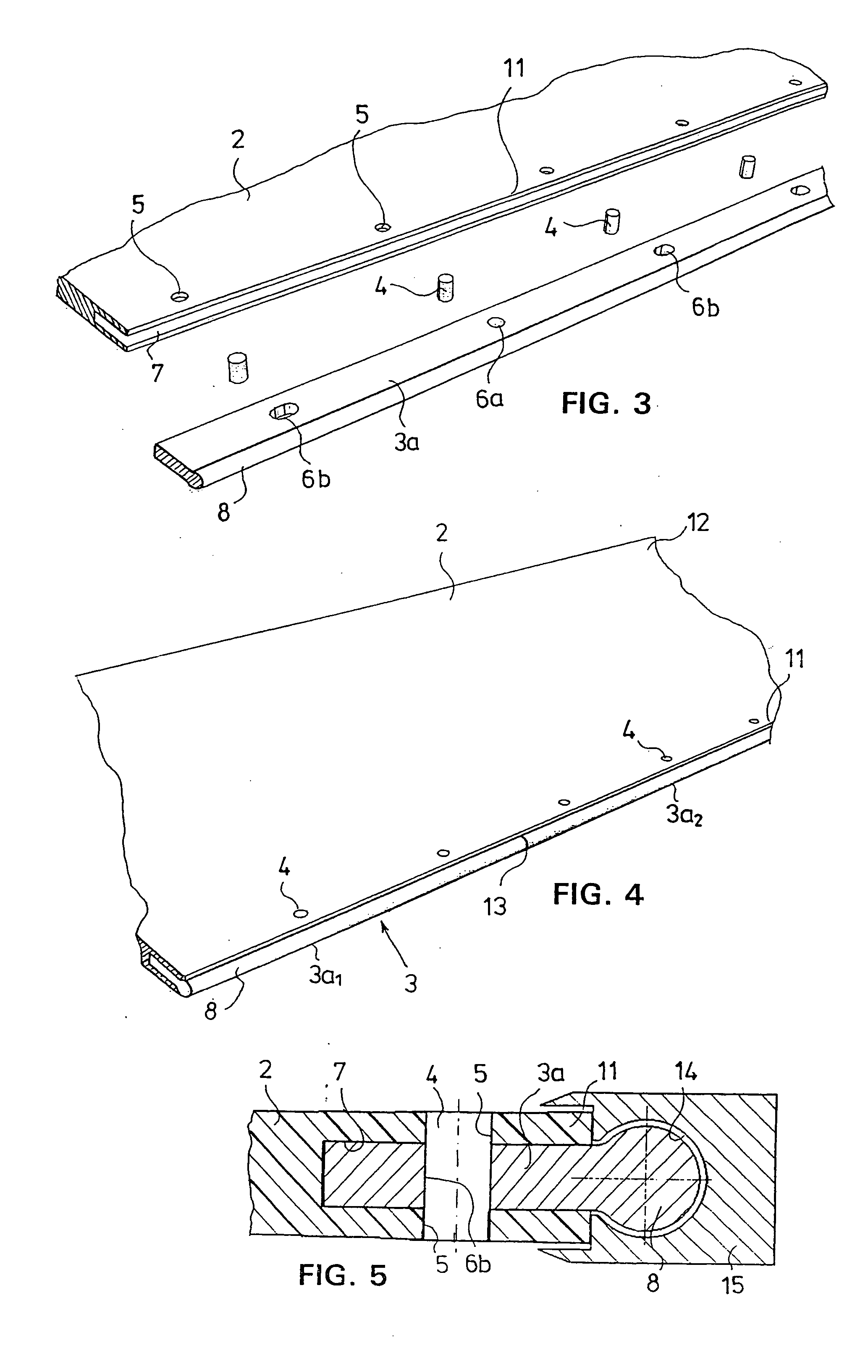
[0023] A headbox vane according to the invention is shown assembled in FIG. 1 and decomposed into parts in FIG. 2. The vane 1 comprises a vane component 2 and a pivot member 3 connected to its inlet edge, by means of which the vane can be fastened to an engagement groove in a headbox, as shown in FIG. 5. The cross section of the vane component 2 is wedge-like such that its thickness reduces from the inlet edge 11 towards the outlet edge 12. The inlet edge 11 is intended to be fastened to the headbox by means of the pivot member 3, and the outlet edge 12 is intended to float freely in the slice chamber flow of the headbox.

[0024] At the inlet edge 11 of the vane component 2 there is machined an opening 7 extending in the longitudinal direction of the vane 1, which is intended to receive the pivot member 3. The pivot member 3 is composed of three longitudinal pivot member elements 3a1, 3a2, 3a3 arranged successively in the opening 7. These are fastened to the vane component 2 by means...


PUM


Abstract

A paper machine headbox vane has a vane component (2) and a pivot member (3) connected together with anchoring elements (4), which pass through holes (5, 6a, 6b) provided in both components (2, 3). The vane (1) is fastened to a headbox engagement groove in the headbox by the pivot member (3) which has two or more pivot member elements (3a1, 3a2, 3a3) which have positioning holes for positioning the vane component (2) and the pivot member elements (3a1, 3a2, 3a3) in relation to each other. A least one longitudinal hole in each element allows its free linear movement in relation to the vane component (2). The vane component (2) has a longitudinal opening (7), which receives the pivot member (3) with an opening between two successive pivot member elements (3a1, 3a2, 3a3). The vane component (2) and the pivot member elements (3a1, 3a2, 3a3) can be of different materials.

Description

CROSS REFERENCES TO RELATED APPLICATIONS [0001] This application claims priority on Finnish Application 20046338, Filed Mar. 3, 2004, the disclosure of which is incorporated by reference herein. STATEMENT AS TO RIGHTS TO INVENTIONS MADE UNDER FEDERALLY SPONSORED RESEARCH AND DEVELOPMENT [0002] Not applicable. BACKGROUND OF THE INVENTION [0003] The invention relates to a vane for the headbox of a paper machine or the like comprising a vane component and a pivot member connected together with anchoring elements, which pass through the holes provided in both components. The vane is intended to be fastened to an engagement groove in the headbox by means of a pivot member. [0004] The paper machine or the like is used to refer to a paper, board or tissue machine. [0005] Vanes are used in the slice channel of a headbox for attenuating large-scale turbulence and for converting it to small-scale turbulence, which prevents formation of fiber bundles and improves the quality of the paper produ...

Claims


Application Information

Patent Timeline
IPC IPC(8): D21FD21F1/02D21F3/02F03B1/04
CPCD21F1/028D21F1/026
Inventor LAPPI, JANNE
Owner VALMET TECH INC
Learn More