
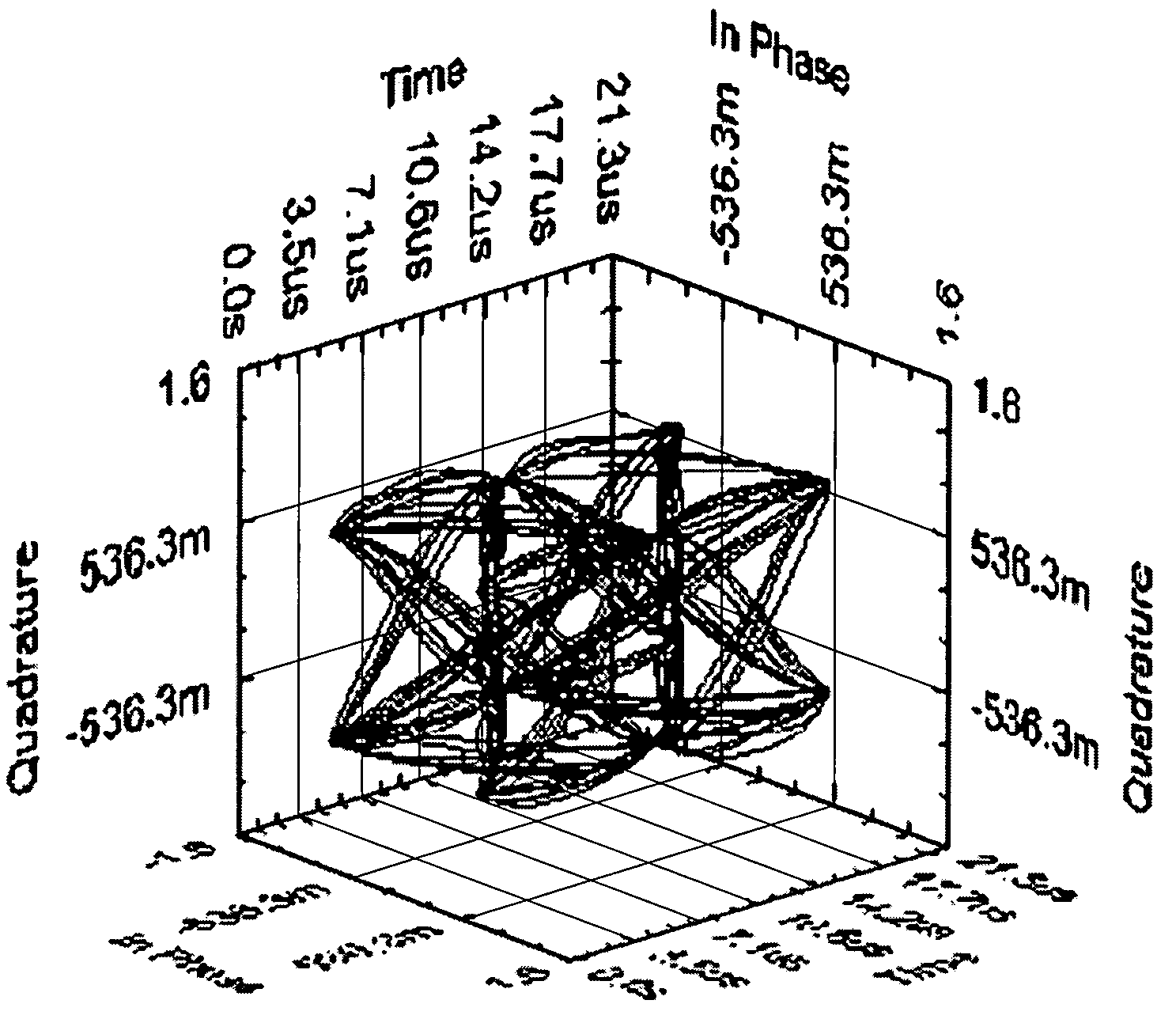
3-D eye diagram

Inactive Publication Date: 2005-09-08
NATIONAL INSTRUMENTS
View PDF5 Cites 9 Cited by
  • Summary
  • Abstract
  • Description
  • Claims
  • Application Information

AI Technical Summary

Benefits of technology

[0023] As noted above, the utility of a 3D eye diagram may be substantially enhanced by manipulating the diagram, e.g., by changing the view angle, projecting the diagram onto various planes, adding auxiliary information, and so forth. Thus, in one embodiment, a graphical user interface (GUI) may be provided for specifying, creating, editing, and viewing 3D eye diagrams. Various embodiments of such a GUI or tool for 3D eye diagrams are described below. It should be noted that the embodiments described herein are intended to be exemplary only, and are not intended to limit the implementation, appearance, or functionality of the 3D eye diagram tool or GUI to any particular form.
[0024] In simple embodiments of the 3D eye diagram tool, the tool may primarily receive signal data, process the data as described above, and display the data in a 3D eye diagram, optionally allowing the user to rotate the diagram in 3D or otherwise project the diagram onto desired planes. Thus, the GUI may include a display area or panel for displaying the generated 3D eye diagram. However, in preferred embodiments, the 3D eye diagram tool may facilitate specification of many aspects of the diagram by the user. In other words, in a preferred embodiment, the method described above may include receiving user input specifying one or more attributes of the 3D eye diagram, and displaying the 3D eye diagram in accordance with the specified attributes.

Problems solved by technology

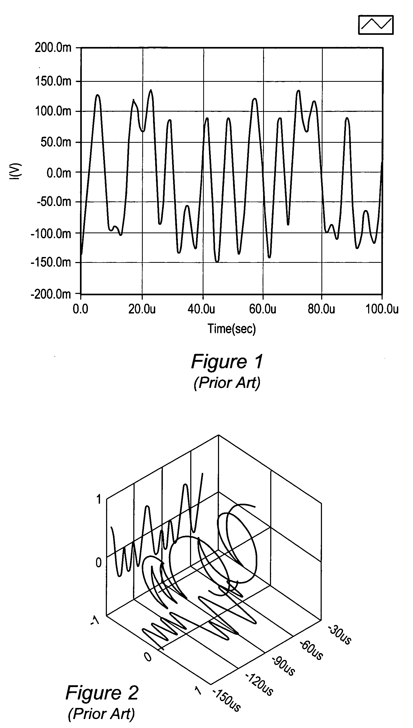
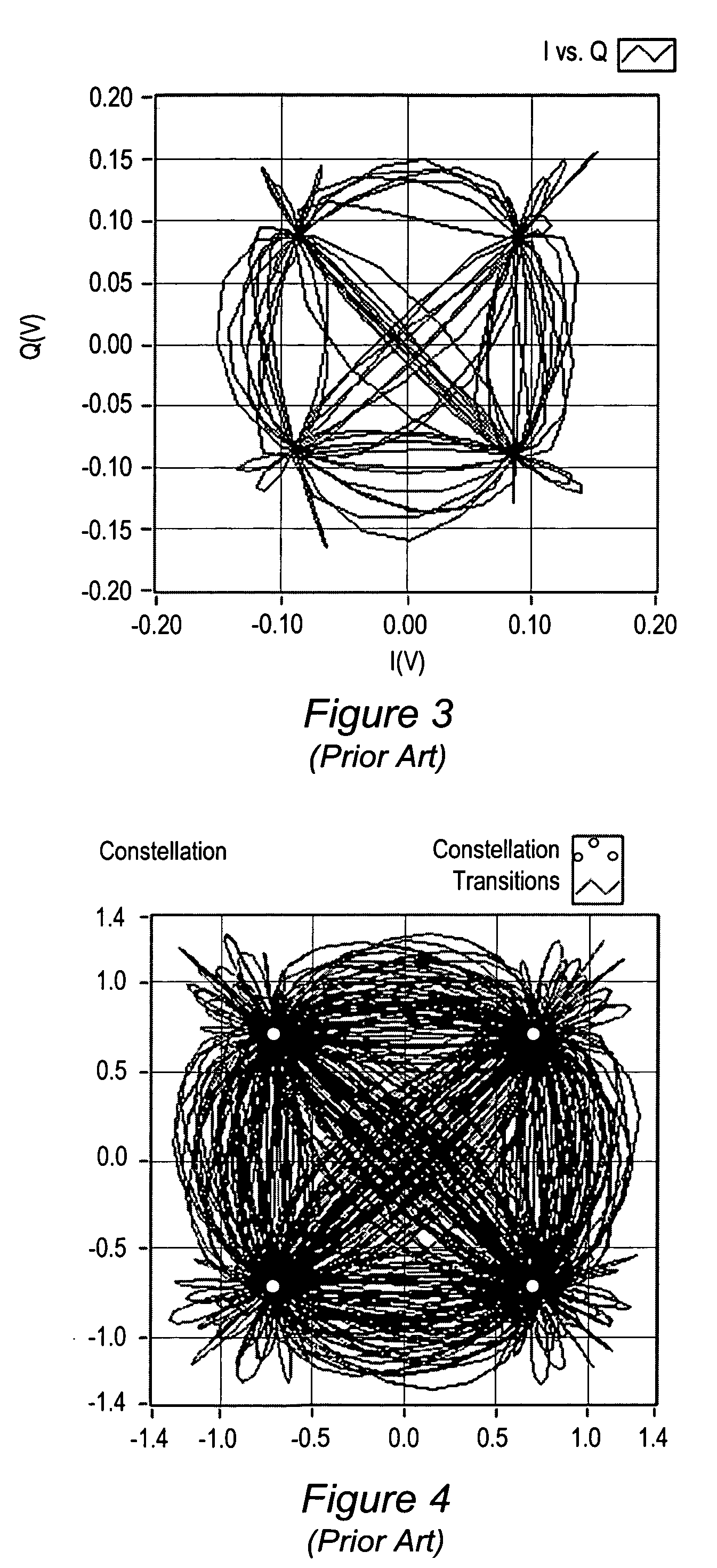
However, the transmitted / received signal is typically filtered, and so this periodicity may not be readily apparent.

Method used


Image

  • 3-D eye diagram
  • 3-D eye diagram
  • 3-D eye diagram

Examples


— example implementation

FIGS. 18-20—Example Implementation

[0145]FIGS. 18-20 illustrate various aspects of an implementation of the 3D eye diagram tool, according to one embodiment. In one embodiment, program elements may be provided for including the 3D eye diagram functionality in an application, e.g., in the form of a toolkit or equivalent. For example, in one embodiment, the toolkit may include graphical program elements that may be used to implement and invoke the above-described functionality in a graphical program, such as a LabVIEW graphical program developed under the LabVIEW graphical programming system provided by National Instruments Corporation. It should be noted, however, that in other embodiments, the 3D eye diagram functionality may be implemented and / or invoked in other types of programs, such as text-based programs, e.g., in C, C++, or JAVA, or in other types of graphical programs. Additionally, in some embodiments, the 3D eye diagram functionality may be implemented and invoked as a stan...


PUM


Abstract

System and method for analyzing signals. Signal data corresponding to a signal is received, e.g., from a data acquisition device, and processed to generate formatted signal data, including segmenting the signal data based on the a period of the signal data to generate segments. The formatted signal data is displayed in a three dimensional (3D) eye diagram by plotting the segments in an overlaid manner, which is usable to analyze the signal. User input may be received specifying attributes of the 3D eye diagram, e.g., zoom, rotation, translation, stereoscopy, display device, plot colors and line styles, point colors and styles, symbol rate, eye length, number of segments to display, projections, e.g., for generating I- or Q-eye diagrams or constellation diagrams, auxiliary information display, e.g., highlight points for symbol timing and / or additional points for ideal symbol locations, data sources, etc., and the 3D eye diagram displayed according to the specified attributes.

Description

FIELD OF THE INVENTION [0001] The present invention relates to a system and method for performing signal analysis. More particularly, a system and method for creating and using a three dimensional (3D) eye diagram to display and analyze data associated with data and communication signals is presented. DESCRIPTION OF THE RELATED ART [0002] Signal communications have become central to many aspects of the modern world. In fact, virtually all modern business, manufacturing, engineering, and scientific enterprises rely substantially on signal communications to perform their activities. To support this ubiquitous phenomenon, a vast and varied technological infrastructure has been, and continues to be, developed, including wireless and wired telecommunications media, fiber-optic components, routers, transmitters, analog and digital signal processing chips, and myriad software programs for managing, processing, analyzing, and transmitting these signals, among others. These communications re...

Claims


Application Information

Patent Timeline
IPC IPC(8): H03F3/04
CPCH04L1/205
Inventor CUMMINGS, ALAN K.
Owner NATIONAL INSTRUMENTS
Learn More