
System and method for displaying chassis component information

Active Publication Date: 2005-09-08
HEWLETT-PACKARD ENTERPRISE DEV LP
View PDF11 Cites 71 Cited by
  • Summary
  • Abstract
  • Description
  • Claims
  • Application Information

AI Technical Summary

Benefits of technology

[0004] The present invention provides a system and method for displaying chassis component information that substantially eliminates or reduces at least some of the disadvantages and problems associated with previous display systems and methods.
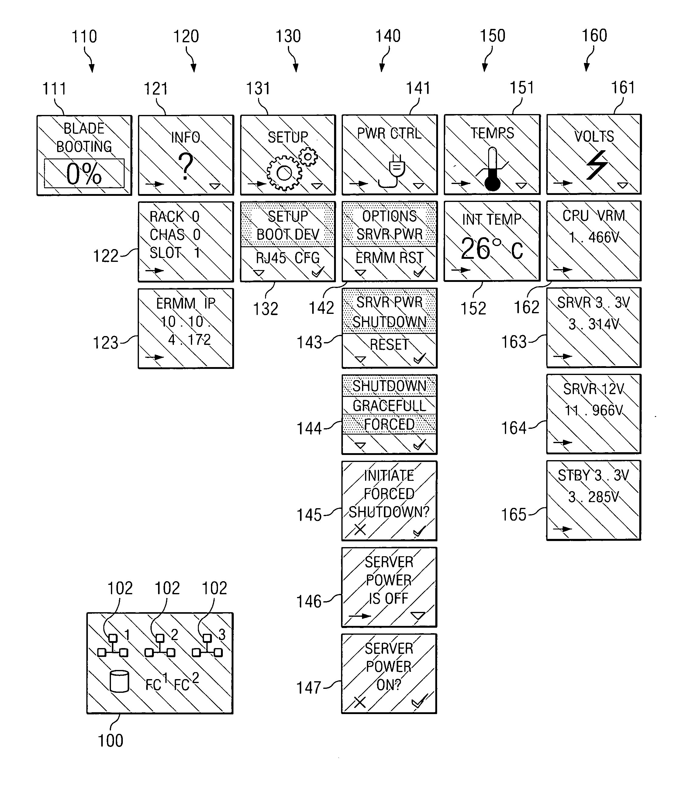
[0010] Technical advantages of particular embodiments of the present invention include a plurality of server blades each having a respective LCD for displaying server blade and other chassis component information. Such information may include activity, health, status and configuration information. Accordingly, a greater amount of information may be displayed on each server blade. Moreover, network configuration information may also be constantly displayed for observation by a user thus reducing the need to couple an external device in order to view such information.
[0011] Another technical advantage of particular embodiments includes the use of associated control keys in connection with an LCD positioned upon a chassis blade. This provides a user with the ability to control chassis operations such as component setup and configuration using the control keys and the LCD. Accordingly, labor expenses and service time with respect to the chassis components may be reduced.

Problems solved by technology

Such increase limits the amount and type of information that can be easily displayed using the LEDs.

Method used


Image

  • System and method for displaying chassis component information
  • System and method for displaying chassis component information
  • System and method for displaying chassis component information

Examples


Embodiment Construction

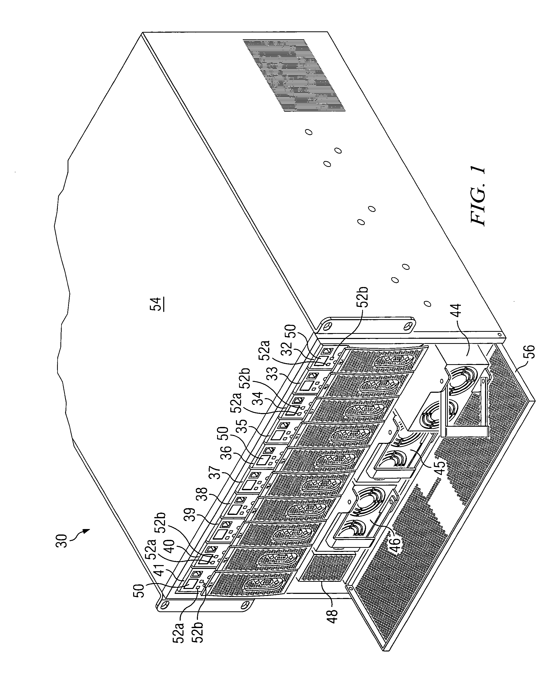
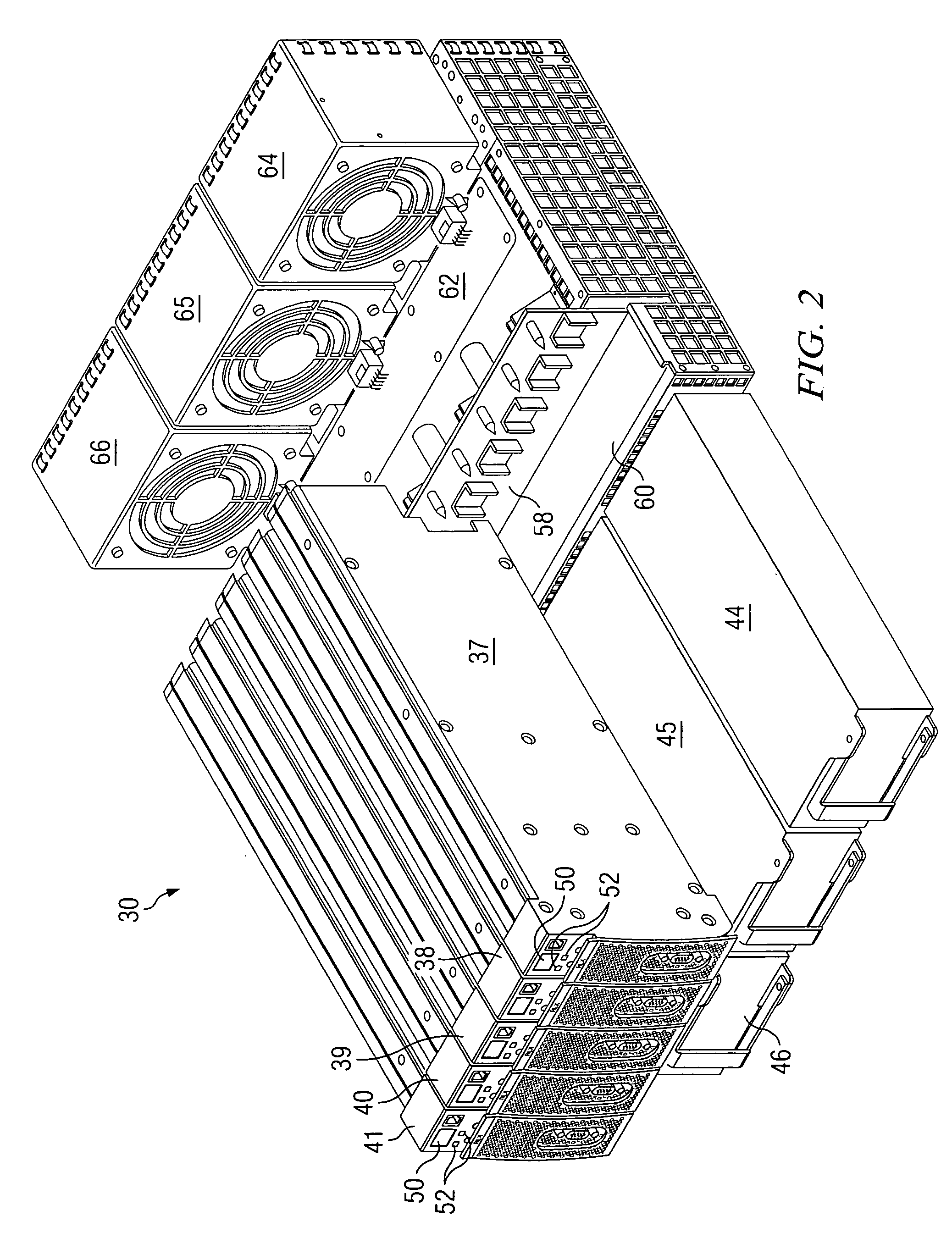
[0020]FIG. 1 illustrates a multiple server blade chassis 30, in accordance with a particular embodiment of the present invention. Server blade chassis 30 includes a plurality of server blades 32-41. Server blade chassis 30 also includes a plurality of network interface cards to provide server blades 32-41 access to one or more communication networks, as further illustrated and discussed below with respect to FIG. 3. In the illustrated embodiment, server chassis 30 is a 6U×28″ chassis configured to receive up to ten server blades and provide access to a plurality of independent networks. The chassis size and number of server blades and / or network interface cards included with server blade chassis 30 may vary significantly within the teachings of the present invention. For purposes of this specification, a “blade” may include a card or other device comprising a printed circuit board and related components operable to be inserted into a chassis for coupling with other cards or network ...


PUM


Abstract

A system for displaying chassis component information includes a chassis and a plurality of server blades each coupled to the chassis. Each server blade comprises a respective liquid crystal display (LCD) positioned upon the server blade. The respective LCD is operable to display chassis component information.

Description

TECHNICAL FIELD OF THE INVENTION [0001] The present invention relates generally to server chassis communication systems and, more particularly, to a system and method for displaying chassis component information. BACKGROUND OF THE INVENTION [0002] Network servers are often used for storage of information, communication and / or to provide access to communication networks including the Internet. Users of network servers are provided the ability to view, access, retrieve and / or store audio, video, data graphics and / or text files. Such files may be displayed to the user via protocols, including, without limitation, hypertext transfer protocol (HTTP). Network servers may include one or more server processing cards coupled with a server chassis. Each server processing card may include software and / or hardware components necessary to perform the functionality of a server. [0003] Light emitting diodes (LEDs) are sometimes used to display activity information relating to the server chassis an...

Claims


Application Information

Patent Timeline
IPC IPC(8): G06F1/18G06F11/32
CPCG06F1/18G06F1/182H05K7/1498G06F11/328H05K7/1494G06F11/3044
Inventor MCGRAW, MONTGOMERY C.MCCLUNG, ROBERT THOMASCOX, GABRIEL C.EATON, DANIEL W.NALLEY, JONATHAN
Owner HEWLETT-PACKARD ENTERPRISE DEV LP
Learn More