
System for monitoring the temperature of wheel bearings in railroad cars

a technology for wheel bearings and temperature monitoring, which is applied in the direction of railway signalling, railway signalling and safety, railway profile gauges, etc., can solve the problems of false response of ir radiation sources, poor sensitivity of ir detectors, etc., and achieve poor sensitivity

Inactive Publication Date: 2005-09-08
MATZAN EUGENE
View PDF11 Cites 33 Cited by
  • Summary
  • Abstract
  • Description
  • Claims
  • Application Information

AI Technical Summary

Benefits of technology

[0008] The system provided by the invention improves heretofore-proposed systems such as disclosed in U.S. Pat. Nos. 3,629,572; 3,697,744; 3,731,087; 3,812,343; and 4,659,043, which include the wayside systems relying on detection of infrared signatures from overheated bearings. The present invention provides an on-board system, which is continuously operating thereby enabling real time detection of bearing failures due to lack of lubrication or mechanical defects as evidenced by overheating. The wayside IR detectors also frequently suffer from poor sensitivity; are widely spaced so that they may not detect an overheated bearing in time to prevent an accident; are not responsive to scanning bearings of cars wherein several (say, three) different sizes of wheels are employed; are prone to falsely respond to sources of IR radiation other than the car bearings.

Problems solved by technology

The wayside IR detectors also frequently suffer from poor sensitivity; are widely spaced so that they may not detect an overheated bearing in time to prevent an accident; are not responsive to scanning bearings of cars wherein several (say, three) different sizes of wheels are employed; are prone to falsely respond to sources of IR radiation other than the car bearings.

Method used


Image

  • System for monitoring the temperature of wheel bearings in railroad cars
  • System for monitoring the temperature of wheel bearings in railroad cars
  • System for monitoring the temperature of wheel bearings in railroad cars

Examples


Embodiment Construction

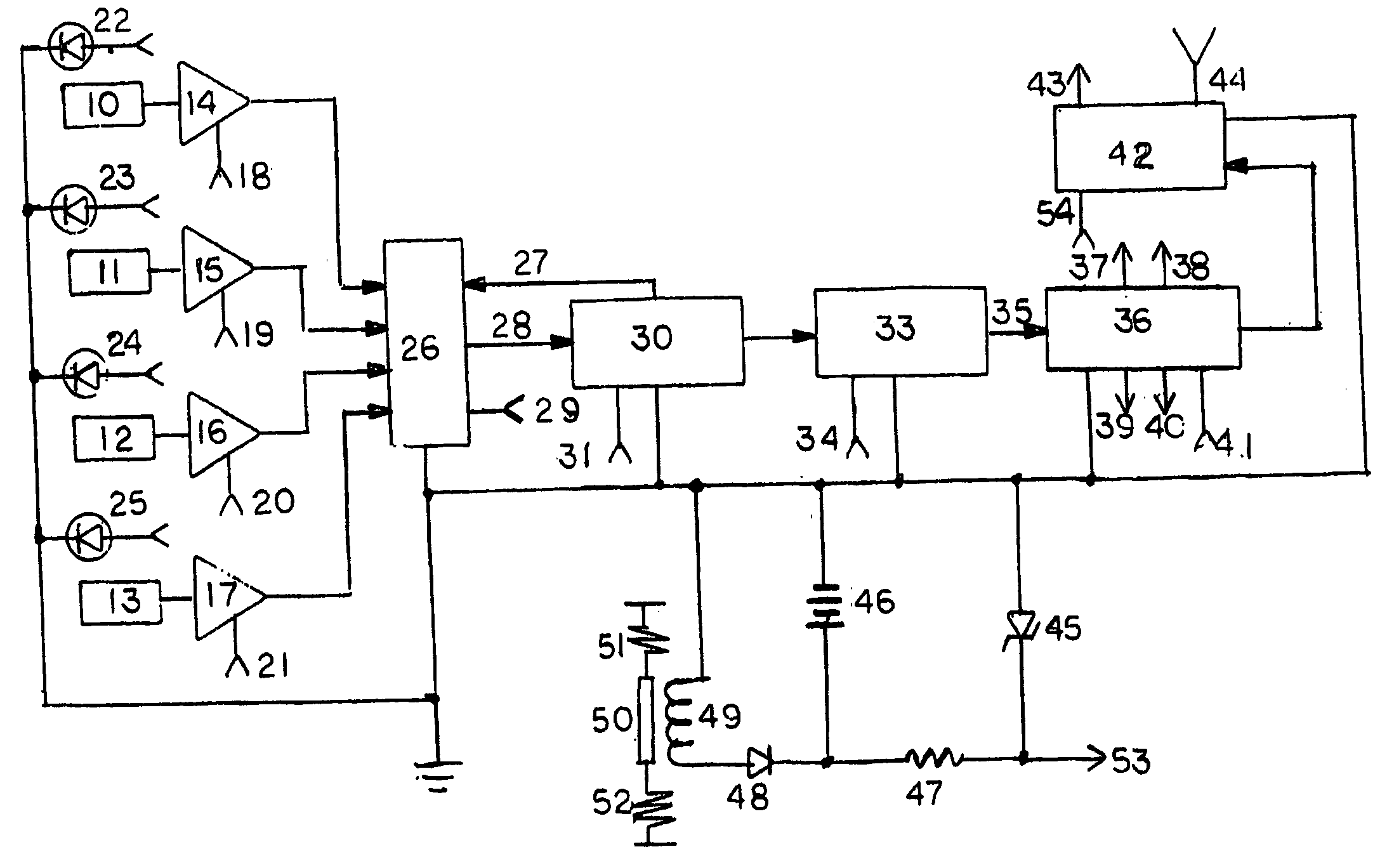
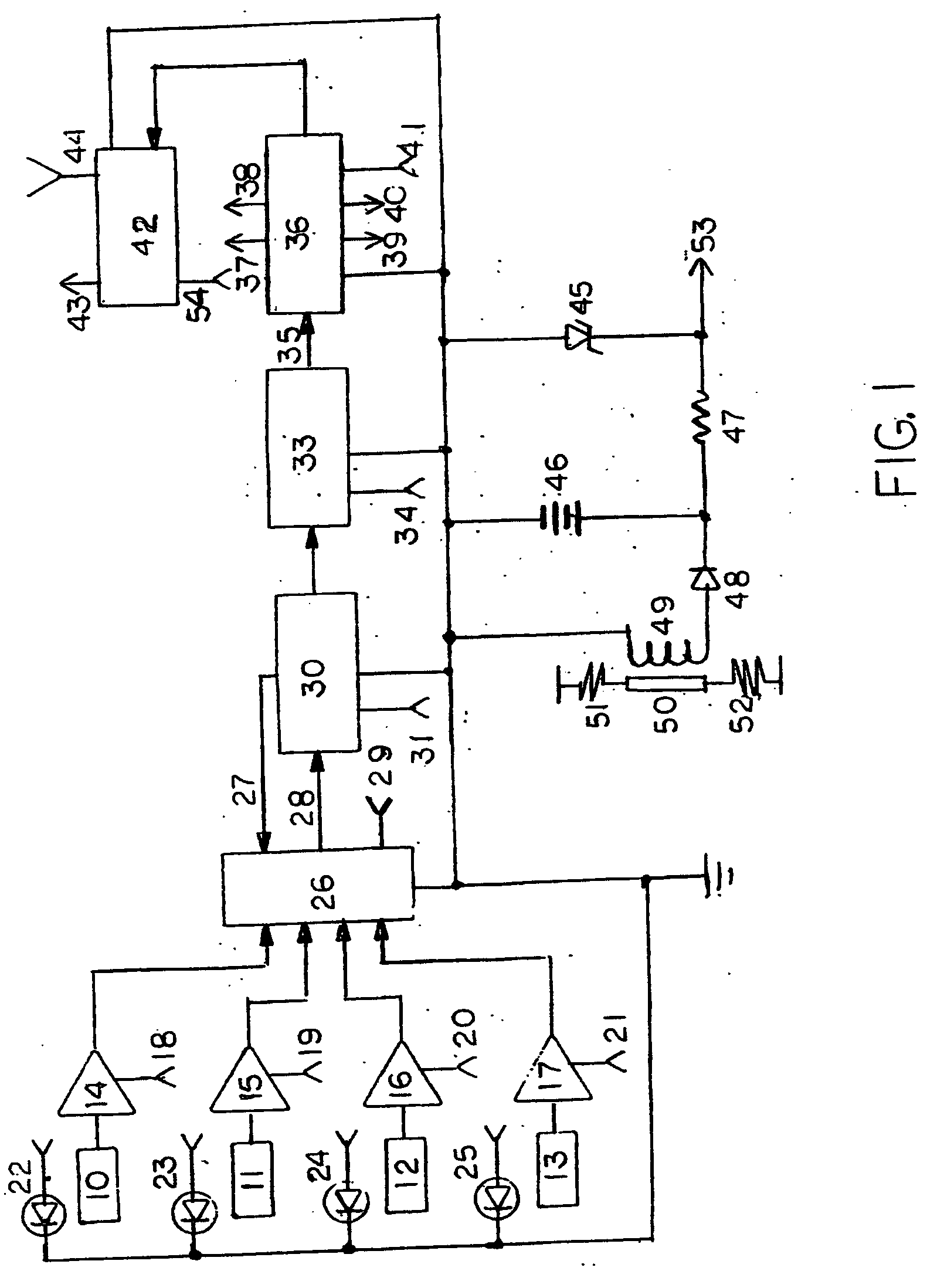
[0012] With reference to FIG. 1, temperature sensors 10, 11, 12, and 13 are installed in close proximity to the bearings of each of the wheels of a railroad car or carriage. Railroad cars usually have four axles and eight wheels, however, only the sensors for four wheels are shown; the sensors for all eight wheels are identical. The sensors generate electrical signals analog to the temperature of these bearings. The signals are amplified by the amplifiers 14, 15, 16, and 17 and passed on to a multiplexer module 26, which contains a solid state switching circuit that continuously cycles, serially selecting inputs from amplifiers 14, 15, 16, and 17 and directing the signals from these inputs to the output 28. The cycling is controlled by the clock signals from the module 30 via line 27.

[0013] Module 30 is an A / D converter that converts the signals analog to the bearing temperature into digital data. Module 30 also contains a digital clock and a circuit for imparting a string of code ...


PUM


Abstract

A system is described for automatic detection of overheated wheel bearings of railroad cars and carriages. Signals representing the temperature of such bearings are generated by temperature sensors that are installed in close proximity of the wheel bearings. The signals are amplified, digitized and, to prevent false indications, averaged for each individual bearing. The averaged signals from each bearing are than compared to the averaged signals from the other three bearings of the same car or vehicle. If the signal from any bearing deviates by a present magnitude value, an alarm signal is generated and transmitted to a central monitoring location. The signals from each bearing are uniquely identified by a code. Light emitting diodes are installed close to the bearings and light up to indicate overheating. The electric power for the system is generated by an electromagnetic generator, which responds to the vibrations of the moving car.

Description

[0001] This application claims priority to my provisional application 60 / 550,432 filed Mar. 8, 2004, which by this reference is incorporated herein.FIELD OF INVENTION [0002] The instant invention relates generally to systems for detecting defects in wheel bearings of railroad car due to overheating by monitoring the temperature of such bearings. BACKGROUND OF THE INVENTION [0003] Overheating of wheel bearings in railroad cars can lead to serious accidents if not noticed before major damage occurs. The Office of Safety Analysis of the Federal Railroad Administration reports that during the period between January and November 2003 there have been 1,477 train accidents attributable to equipment defects and failures. In fact, 180 of such incidents were directly related to bearing or breaks failures (See “Federal Railroad Administration, 2003 Report on Train Accidents due to Equipment Failures”). Such accidents are especially dangerous when they involve passenger carriages and freight ca...

Claims


Application Information

Patent Timeline
Patent Type & Authority Applications(United States)
IPC IPC(8): B61L3/00
CPCB61K9/04
Inventor MATZAN, EUGENE
Owner MATZAN EUGENE
Learn More