
Learning apparatus and method for variable valve control of internal combustion engine

a technology of variable valve and learning apparatus, which is applied in the direction of non-mechanical valves, engine starters, instruments, etc., can solve the problems of accelerating biting, roughening and wear of sliding parts, and the possibility of making the engine stability considerably worse, so as to reduce the responsiveness, the learning time is longer, and the friction resistance is reduced

Active Publication Date: 2005-09-08
NISSAN MOTOR CO LTD
View PDF3 Cites 17 Cited by
  • Summary
  • Abstract
  • Description
  • Claims
  • Application Information

AI Technical Summary

Benefits of technology

[0003] Under a condition where a crankshaft has stopped rotating and link constituent parts of a variable valve operating mechanism are actually not moving, a stationary friction coefficient at a linked portion such as a slide bearing is large and a frictional resistance thereat is also large. Accordingly, if a control shaft is driven toward a reference position under a condition where the crankshaft has stopped rotating, i.e., before start or after stop of an engine, a driving energy of an actuator becomes so large, thus causing a possibility of making longer a learning time due to a large-sized actuator and a lowered responsiveness and accelerating biting, roughening and wear of sliding portions.
[0005] It is accordingly an object of the present invention to provide a learning apparatus and method for a variable vale control of an internal combustion engine that can make smaller a driving energy of an actuator for driving a control shaft without incurring a deterioration of a combustion stability and can rotationally drive the control shaft to a reference position rapidly and assuredly.

Problems solved by technology

Accordingly, if a control shaft is driven toward a reference position under a condition where the crankshaft has stopped rotating, i.e., before start or after stop of an engine, a driving energy of an actuator becomes so large, thus causing a possibility of making longer a learning time due to a large-sized actuator and a lowered responsiveness and accelerating biting, roughening and wear of sliding portions.
On the other hand, during actual operation of the engine, fuel is supplied to a combustion chamber and burnt to produce a driving force.
Thus, if the control shaft is driven to a minimum operation angle position that is a reference position, during such actual operation of the engine, there is a possibility of making the engine stability considerably worse.
Accordingly, if the control shaft is moved into the minimum angular position during actual operation of the engine for learning, a desired intake air quantity cannot be attained, thus deteriorating the combustion condition and lowering the engine stability.

Method used


Image

  • Learning apparatus and method for variable valve control of internal combustion engine
  • Learning apparatus and method for variable valve control of internal combustion engine
  • Learning apparatus and method for variable valve control of internal combustion engine

Examples


first embodiment

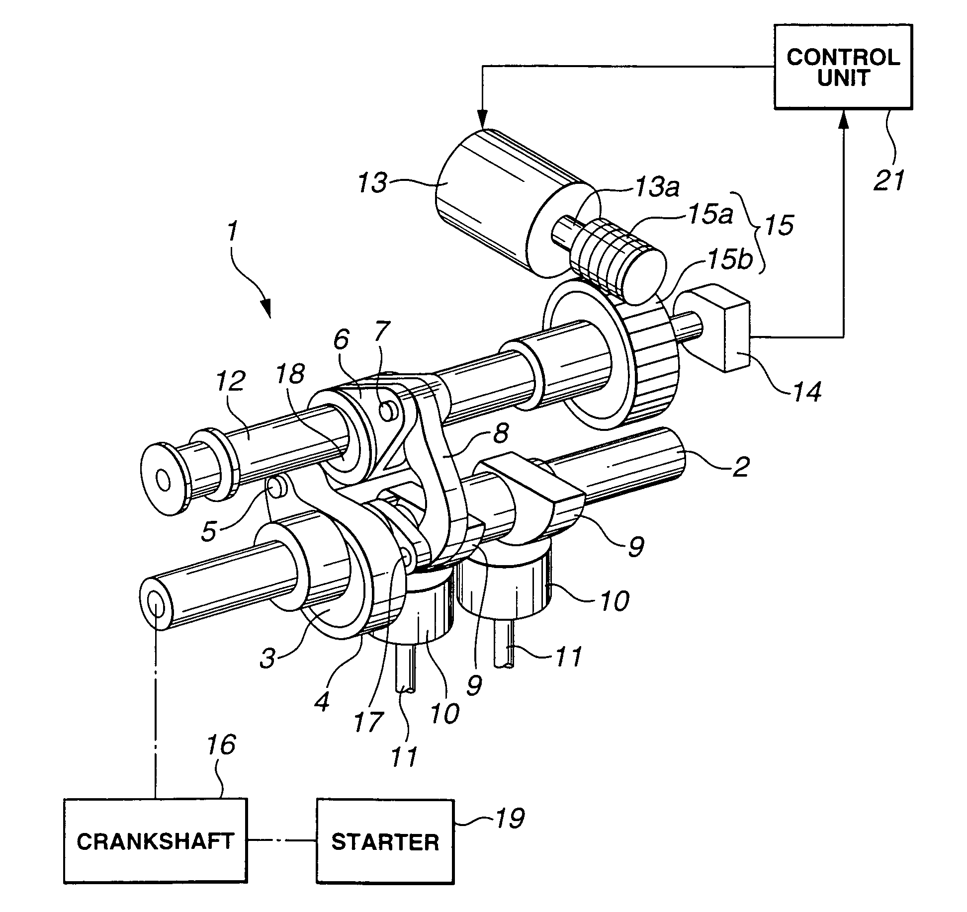
[0022] Referring first to FIG. 1, a learning apparatus for a variable valve control of an internal combustion engine according to the present invention includes variable valve operating mechanism 1 which is shown as constituting a variable valve event and lift mechanism (VEL) that is mechanically connected to crank shaft 16 of the internal combustion engine so as to drive intake valves 11 to open and close in timed relation with rotation of crankshaft 16 while being capable of continuously varying lift characteristics of intake valves 11 in dependence upon rotation of control shaft 12, more specifically both of valve lift and operation angle of intake valve 11. Since an example of variable valve operating mechanism 1 is disclosed in Unexamined Japanese Patent Publication No. 2003-41955, brief description will be made thereto.

[0023] Variable valve operating mechanism 1 includes drive shaft 2 rotatably supported on a cam bracket (not shown) that is disposed at an upper part of a cylin...

sixth embodiment

[0048] In the present invention, a control routine shown in FIG. 14 is executed immediately before stoppage of the engine, in addition to the control routine at start of the engine, that is shown in FIG. 12. The control immediately before stoppage of the engine (FIG. 14) is combined with the control at start of the engine (FIG. 12).

[0049] Referring to FIG. 14, similarly to the first embodiment, in step S31, the routine is started when the ignition switch is switched from ON to OFF, i.e., when a driver's requirement for stoppage of the engine is detected. In the subsequent step S32, supply of fuel is stopped. In step S33, control shaft 12 is rotationally driven toward the minimum operation angle position that is the reference position. Then, the control proceeds to step S34 where it is determined whether or not crankshaft 16 has stopped rotating. If it is determined that crankshaft 16 is not rotating but at standstill, the control proceeds to step S35 where the control of driving con...


PUM


Abstract

A learning apparatus for a variable valve control of an internal combustion engine includes a variable valve operating mechanism, an actuator that rotationally drives the control shaft, a control shaft sensor that detects an angular position of the control shaft, a reference position determining section that determines whether or not the control shaft has reached a predetermined reference position under the drive from the actuator, a learning section that learns an output value of the control shaft sensor when it is determined that the control shaft has reached the reference position and stores the learned output value as a sensor output reference value, and a learning preparing section that causes the control shaft to be driven by the actuator toward the reference position when a crankshaft of the engine is rotating and supply of fuel to the engine is stopped. A learning method is also provided,

Description

BACKGROUND OF THE INVENTION [0001] The present invention relates in general to a variable valve operating mechanism for variably controlling lift characteristics of an intake or exhaust valve (hereinafter referred to as intake / exhaust valve) in accordance with an angular position of a control shaft and more specifically to a learning apparatus and method for a variable valve control of an internal combustion engine, particularly for learning and storing a sensor output reference value of a control shaft sensor. [0002] Unexamined Japanese Patent Publication No. 2003-41955 discloses a variable valve operating mechanism for driving an intake / exhaust valve in timed relation with a crankshaft of an internal combustion engine while being capable of varying lift characteristics of the intake / exhaust valve in accordance with a variation of an angular position of a control shaft and a learning system therefor. The system is configured to drive, by means of an actuator, a control shaft to a m...

Claims


Application Information

Patent Timeline
Patent Type & Authority Applications(United States)
IPC IPC(8): F01L13/00F01L1/34F02D13/00F02D13/02F02N11/08F16H53/06
CPCF01L1/267F01L13/0021F01L13/0026F01L2013/0073Y02T10/18F01L2800/14F01L2820/045F02D13/0226F01L2800/09Y02T10/12
Inventor NOHARA, TSUNEYASUAKASAKA, YUUZOUKAWAMURA, KATSUHIKOMIURA, HAJIMENISHII, SATOSHI
Owner NISSAN MOTOR CO LTD
Learn More