Power transmission device for power tool

a transmission device and power tool technology, applied in the direction of gearing, slip coupling, portability drilling machines, etc., can solve the problems of difficult oiling of friction members, difficult to comprehend both set-up conditions, and difficulty in oiling of friction faces, etc., to achieve quick, readily and reliably stop the oiling process

Inactive Publication Date: 2005-09-08
SHIBUYA CO LTD
View PDF5 Cites 3 Cited by
  • Summary
  • Abstract
  • Description
  • Claims
  • Application Information

AI Technical Summary

Benefits of technology

[0007] When divided into two or more sections, the friction faces of the friction members will be formed with gaps through which lubricant is facilitated to flow or by which lubricant is resupplied to the friction faces in a facilitated manner. Upon this division, material shavings generated during slip can be readily discharged together with lubricant. Further, such gaps facilitate divergence of heat generated due to friction. Thus, improvement in resuppliability of lubricant, divergeability of heat, and dischargeability of material shavings will prevent the status of the friction faces under a slip condition from changing suddenly, thereby will further stabilize transmission torque under a slip condition and allow stable and long-hour transmission of torque. Stable torque contributes to good operationality of a power tool under a slip condition, and for instance an operation for stopping a power tool can be effected promptly, readily and credibly. As the friction members, an example can be given where radial or concentric grooves have been formed in a friction face of a toroidal friction member composed of a flat plate. When resuppliability of lubricant, divergeability of heat, and dischargeability of material shavings are taken into consideration, radially-grooved friction members are more preferable than concentrically-grooved ones.
[0008] Although it is conceivable that oiled friction faces of the friction members of the slip clutch will withstand longer-time slip operation, however the friction faces of the friction members are in close contact with the counterparts, so that it is difficult to oil onto the friction faces even if the lubricant is of low viscosity. For example in a hand-held power tool, grease of high viscosity is often used from a viewpoint of maintenance-free operation, to lubricate periphery of the friction members. In such a case, oiling onto the friction members is more difficult than a case where lubricant of low viscosity is used. In this respect, the present invention will be more preferable for stabilizing transmission torque and improving durability of a hand-held power tool in which grease is used for lubrication, because the present invention does not oil onto the friction members but divides them into two or more sections to stabilize the transmission torque under a slip condition and thereby improve durability.
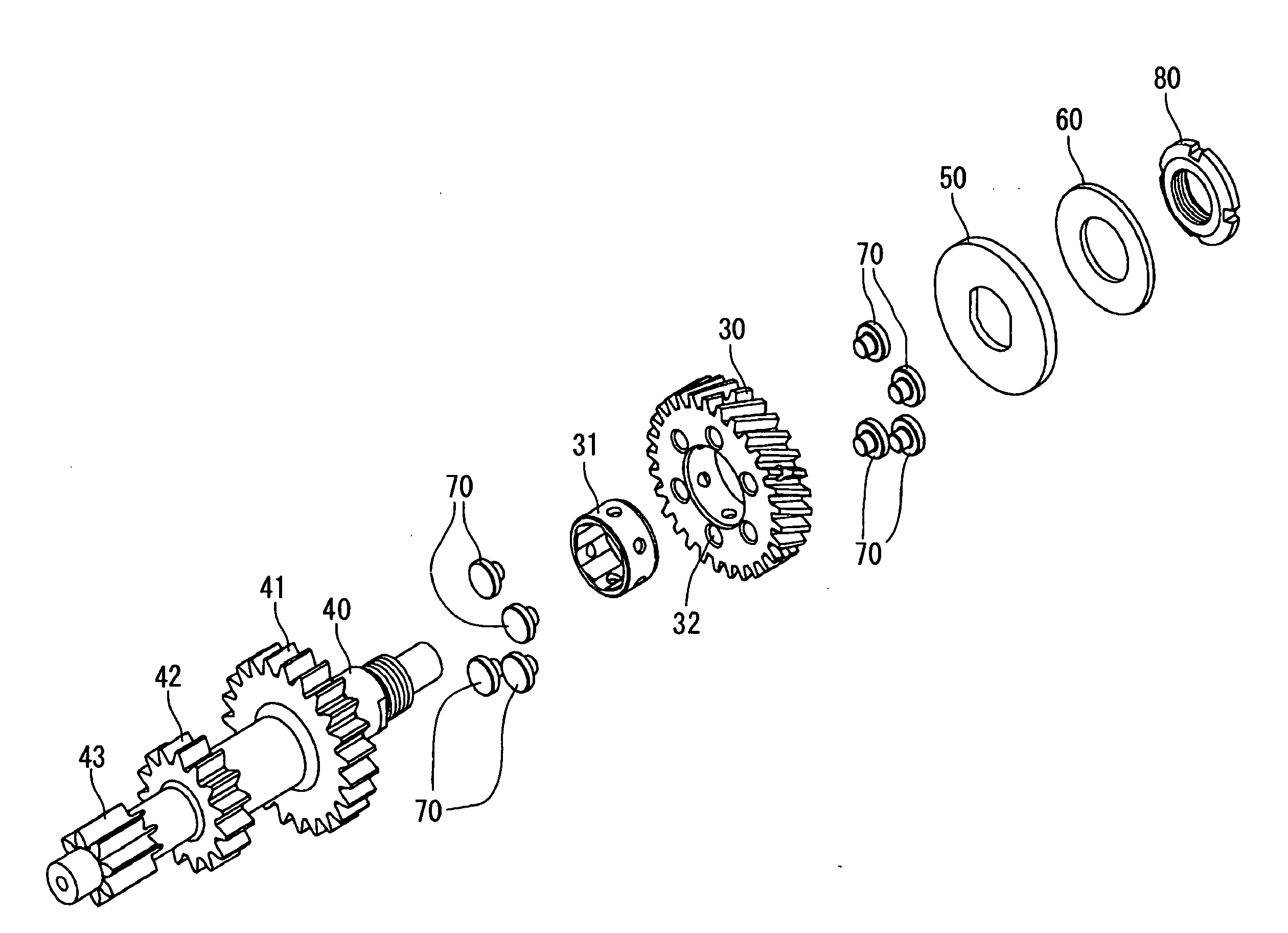
[0010] In view of the above study results, it is preferable if an installation structure of the friction members is such that the friction members should be installed into any of a gear or a rotator, which are in contact with the friction members, rather than the friction members should be held tightly at both sides thereof in a manner as has been conventionally done. Thus, such a structure in which the friction members has been installed into a gear or a rotator will provide single-sided friction faces allows the slip initiation torque to be readily and accurately set up. When assemblability is taken into consideration, it is more preferable if the structure has the friction members installed in the gear.
[0012] Consequently, further studies revealed that it is more preferable if the friction member is comprised of two or more friction members, each of which is independently detachable with respect to the gear and has a friction face. This is ascribable to a fact that the friction face of the friction members according to the present invention is smaller than the counterpart of the conventional tabular toroidal friction members, whereby a friction face with higher face accuracy is readily obtainable. This is also ascribable to an assumption that if friction member pieces having uniform and excellent face accuracy only are selected and used out of a plurality of those independently provided as a friction member, the face accuracy could be improved comparatively readily. According to the present invention, a friction face with higher face accuracy is available, and local imposition of greater pressure is positively prevented. As a result, seizure will be prevented from occurring on a friction face, whereby durability of a power transmission device will be increased.
[0013] A conceivable structure in which each friction member piece should be installed in a gear is for instance that holes into which friction member pieces should be installed are formed in a side face of a gear and into which projections formed on each friction member piece should be inserted in a releasable manner. Such a structure will be advantageous if the number of holes formed in the side face of the gear is relatively large and the number of friction member pieces to be installed into the gear is adjusted to alter the area of the friction face, which is one of face conditions of the friction face. For instance, when the number of holes is six, in addition to a case where all the six holes are installed with friction member pieces, the area of the friction face can be adjusted if the friction member pieces are installed into two, three or four out of the six holes in a stepped manner. If the area of the friction face is successfully adjusted, then flexibility in setting up slip initiation torque which is set up with mainly face conditions of a friction face and pressure will be increased, thereby setting up the set-up torque, i.e. slip initiation torque to desirable torque will be facilitated. It should be noted maximum transmission torque is set up, for instance with rated torque of a motor equipped being taken into consideration.
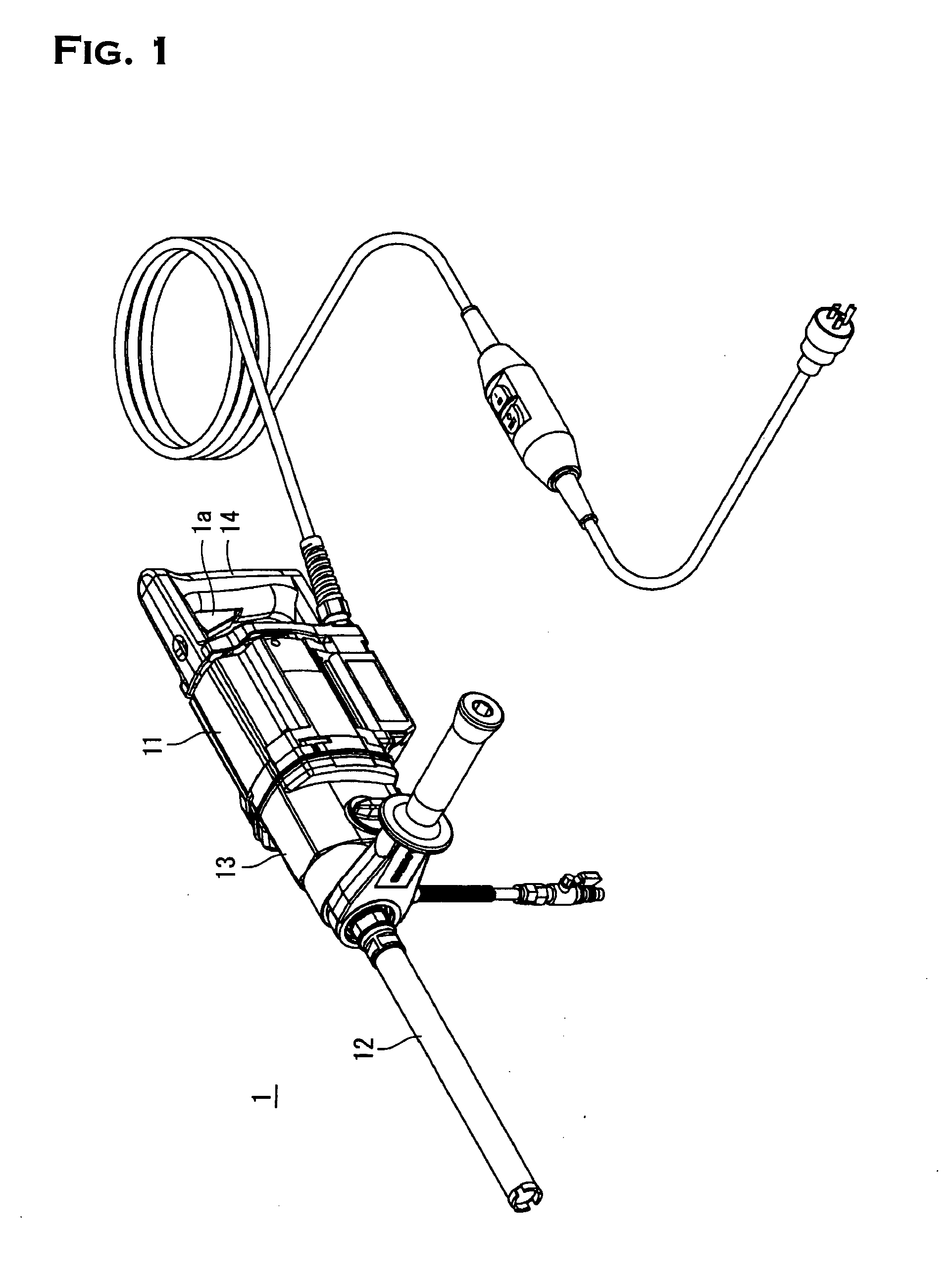
[0015] As described above, the power transmission device for a core drill according to the present invention allows predetermined torque to be transmitted in a stable manner under a slip condition of a slip clutch, whereby excelling in operationality of a power tool under a slip condition. Once operationality is established, the power tool can be stopped quickly, readily and reliably, for instance under a slip condition.

Problems solved by technology

Although it is conceivable that oiled friction faces of the friction members of the slip clutch will withstand longer-time slip operation, however the friction faces of the friction members are in close contact with the counterparts, so that it is difficult to oil onto the friction faces even if the lubricant is of low viscosity.
In such a case, oiling onto the friction members is more difficult than a case where lubricant of low viscosity is used.
However, both sides of the friction plate are two sides of the same plate, which shows an example of no simple peripheral conditions of the friction members, whereby it is not easy to comprehend both the set-up conditions.
In such a case, set-up should be made in conformity with a slippery friction face, however it is actually no easy to determine which is a most slippery friction face.

Method used


Image

  • Power transmission device for power tool
  • Power transmission device for power tool
  • Power transmission device for power tool

Examples


Embodiment Construction

[0023] Hereinafter, preferred embodiments of a core bit according to the present invention will be concretely described with reference to the drawings.

[0024] Symbol “1” in FIG. 1 indicates a so-called hand-held core drill, i.e. power tool. The core drill 1 has a motor 11 as a source of power integrally incorporated therein, and a power transmission section 13, i.e. power transmission device, which transmits rotation of the motor 11 is incorporated between the motor 11 and a core bit 12, i.e. tip tool. The core drill 1 further has a grip 14 on which a switch 1a is provided. Switching on or off the switch 1a operates or stops the core drill 1.

[0025] As FIG. 2 shows, the power transmission section 13 has a gear 30 meshing with a tip gear 21 of an input shaft 20 which transmits rotation of the motor 11. The gear 30 is equipped in a bore thereof with a bush 31, and the bush 31 is pivotally supported in a slidable manner on a first shaft 40 which is rotatably supported on a housing 1b o...


PUM

PropertyMeasurementUnit
frictionaaaaaaaaaa
torqueaaaaaaaaaa
sizeaaaaaaaaaa

Abstract

The present invention relates to a power transmission device for a power tool, more specifically for a core drill, which device is capable of transmitting predetermined torque in a stable manner and for longer period of time under a condition where a clutch slips. The power transmission device for a core drill comprises of: a gear 30 to which rotation from a power source is input; a disk-shaped rotator 41, 50, which is disposed coaxially with the gear 30 and transmits rotation of the gear 30 to the tip tool side; friction members, which are installed between the gear and rotator and kept pressed against the side face or faces of the gear and / or rotator, and said power transmission device transmitting rotation of the gear to the rotator with the use of friction caused between the gear 30 and / or rotator 41, 50 and the friction members, and as friction members, friction members 70 having two or more friction faces 70a which are spaced apart from each other are used.

Description

TECHNICAL FIELD [0001] The present invention relates to a power transmission device for a power tool, which transmits rotation to a tip tool, and particularly relates to a power transmission device characterized by a clutch mechanism. BACKGROUND OF THE INVENTION [0002] A powered tool such as for example a core drill is normally provide at a power transmission device thereof with a clutch to prevent excessive torque from being imposed on a motor as a source of power. A power tool which requires small size and light weight generally adopts so called a slip clutch having a relatively simple structure. The slip clutch is structured to have a disk-shaped or toroidal friction plate comprised of a flat plate held tight between a gear and a clutch disk or a rotational object such as for example a rotary shaft, thereby is adapted to transmit turning force with the use of friction between contact surfaces pressed against each other (see Japanese Patent Application Laid-open No. Hei10-296574)....

Claims


Application Information

Patent Timeline
Patent Type & Authority Applications(United States)
IPC IPC(8): B23B45/00B25F5/00F16D7/02F16D43/21F16H35/10
CPCB23B45/008Y10T74/19847B25F5/001
Inventor SASAGUCHI, NORIYUKIORA, NAOTAKA
Owner SHIBUYA CO LTD
Why Eureka
Try Eureka