
Utility knife

a technology for utility knives and handles, applied in the direction of thrusting weapons, white arms/cold weapons, weapons, etc., can solve the problems of inconvenient opening of the handle, mechanism inusable, and handles can also become worn or damaged

Inactive Publication Date: 2005-09-08
BLACK & DECKER INC
View PDF37 Cites 71 Cited by
  • Summary
  • Abstract
  • Description
  • Claims
  • Application Information

AI Technical Summary

Benefits of technology

[0014] One advantage of a currently preferred embodiment of the above aspect of the present invention is that the nose portion of the housing can be made of a metal that is more wear resistant than conventional steel, and if desired, coated with TiN and / or AlTiN, to improve the durability at the nose (where needed in such embodiment) at lesser cost than would result from using the more wear resistant material and coating, if desired, throughout the entire housing.
[0018] One advantage of the above aspect of the present invention is that the manually operable member for use in releasing the blade does not become separated from the housing when the housing is in the open state.

Problems solved by technology

However, because it is sometimes inconvenient to open the handle, some utility knives provide mechanisms that allow a blade to be removed without any need for first opening the handle.
Unfortunately, upon opening the handle, many of the above mentioned mechanism can fall out and become separated from the handle, thereby rendering the mechanism unusable.
As with blades, handles can also become worn or damaged due to demanding operating conditions, such as for example in the course of regular use in cutting asphalt roof tiles.
However, even knives with steel handles continue to become worn and / or damaged frequently, on account of such operating conditions.

Method used


Image

  • Utility knife
  • Utility knife
  • Utility knife

Examples


Embodiment Construction

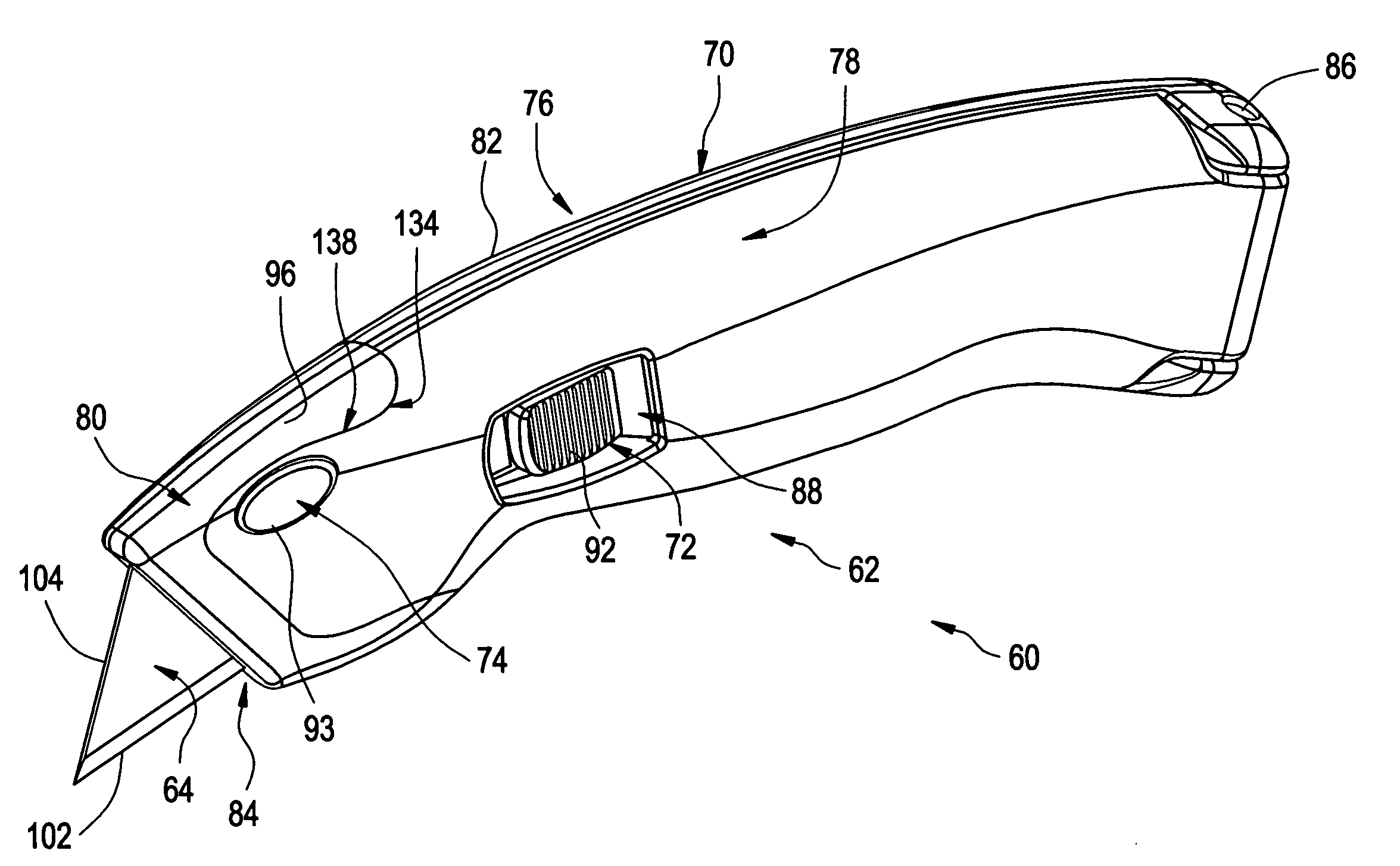
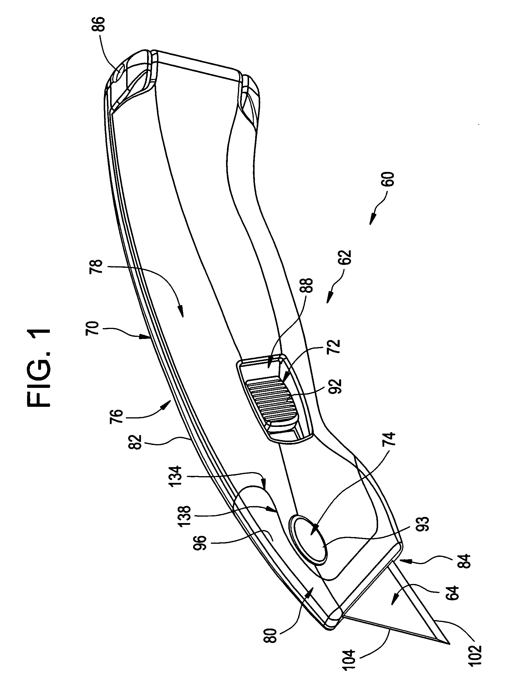
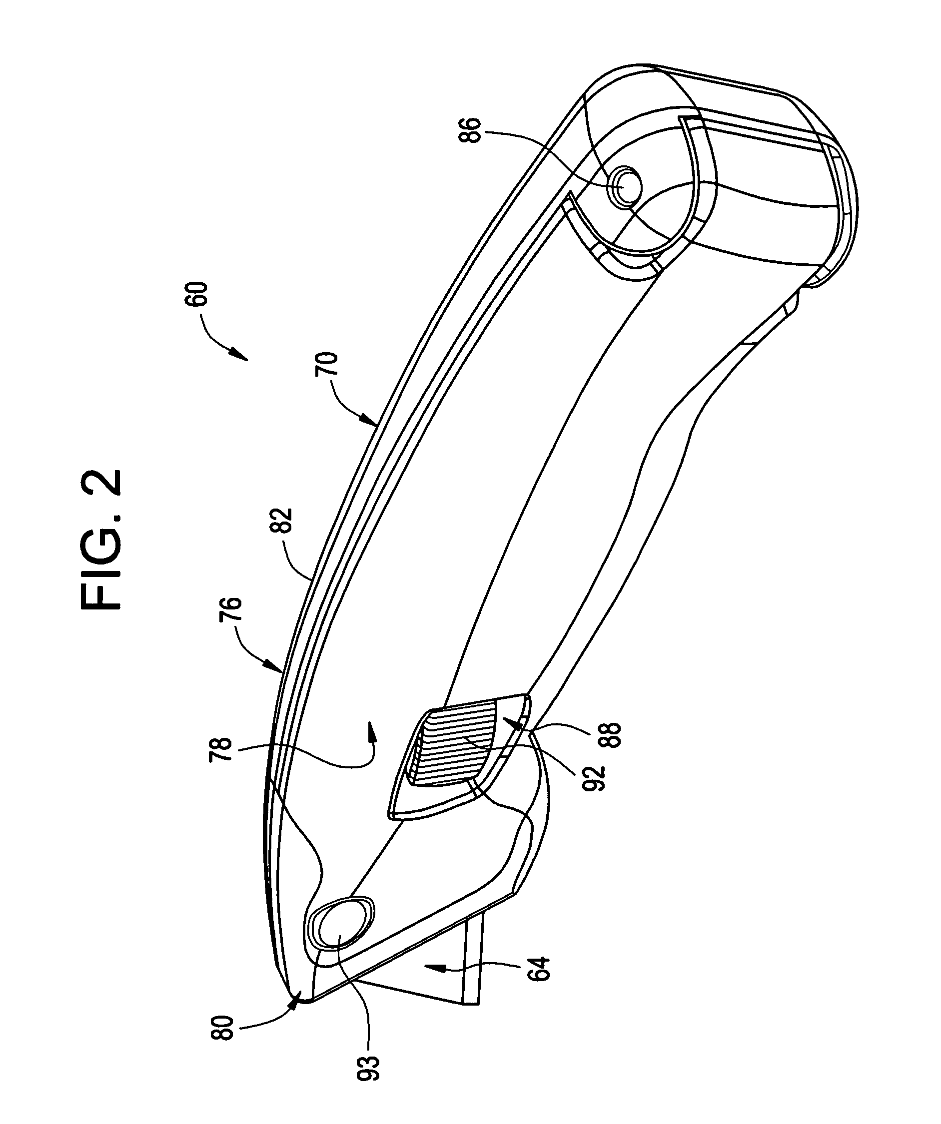
[0057]FIGS. 1-2 show perspective views of a utility knife 60 according to a first embodiment thereof. The utility knife 60 includes a handle 62, a blade 64 and a spare blade assembly 66 (see FIG. 8) for storing spare blades 68 (see FIG. 8). The handle 62 includes a housing 70 (shown in a closed state) defining a substantially internal cavity 71 (FIG. 8), a mechanism 72 for releasably holding the two portions of the housing together (see also FIG. 8) and a mechanism 74 for releasably engaging the blade 64 (see also FIG. 8).

[0058] The housing 70 is formed of two separate portions 76, 78. The first portion 76 is made up of a nose portion 80 and a rear portion 82 disposed rearward of the nose portion 80 (see also FIG. 8). The nose portion 80 defines a blade opening 84 at a first end of the handle 62 to receive the blade 64. The rear portion 82 is, to some extent, a mirror image of the second housing portion 78 and pivotably connected thereto, for example by a fastener (e.g., shown as a...


PUM


Abstract

A handle for a utility knife includes a housing made up of two or more portions. In one embodiment, a manually operable member for use in releasing the blade is retained to at least one portion of the housing and does not become separated from the housing when the housing is in an open state. In another embodiment, a catch for engaging the blade extends from a support member that is slidably movable within the housing. In another embodiment, the housing is formed of metal and a nose portion is formed of a metal that is more wear resistant than the rest of the housing, in order to improve the durability of the nose portion. In another embodiment, a bail screw is captured on a first housing portion and threadedly engageable with a second housing portion for (i) releasably securing the first and second housing portions in a fully closed state and, in turn, releasably securing a blade within the blade opening, and (ii) manually positioning at least one of the first and second housing portions in at least one intermediate state between the fully closed state and a fully opened state to, in turn, permit the blade to be manually moved through the blade opening.

Description

CROSS-REFERENCE TO RELATED APPLICATIONS [0001] This patent application claims priority on U.S. Provisional Patent Application Ser. No. 60 / 518,689, entitled “UTILITY KNIFE”, filed on Nov. 10, 2003, and U.S. Provisional Patent Application Ser. No. 60 / 518,690, entitled “UTILITY KNIFE WITH ACTUATOR FOR MOVING BLADE CARRIER AND FOR RELEASING BLADE THEREFROM, AND RELATED METHOD”, filed on Nov. 10, 2003, each of which is hereby expressly incorporated by reference as part of the present disclosure. This patent application also discloses subject matter similar to that disclosed in the following co-pending patent applications, each of which also is hereby expressly incorporated by reference as part of the present disclosure: U.S. Design Application Serial No. 29 / 193,538, filed on Nov. 10, 2003, entitled “UTILITY KNIFE”; U.S. Design Application Serial No. 29 / 193,524, filed on Nov. 10, 2003, entitled “UTILITY KNIFE”; U.S. Design Application Serial No. 29 / 193,586, filed on Nov. 11, 2003, entitle...

Claims


Application Information

Patent Timeline
Patent Type & Authority Applications(United States)
IPC IPC(8): B26BB26B1/08B26B3/06B26B5/00
CPCB26B5/001
Inventor BROWN, DONALD A.FLEURY, KEVINKORD, WILLIAM B.LEBLANC, NORMANLEVINE, STEVEN R.TALBOT, COREY M.
Owner BLACK & DECKER INC
Learn More