
Ankle prosthesis and method for implanting ankle prosthesis

a technology of ankle prosthesis and implants, which is applied in the field of ankle prosthesis, can solve the problems of large amount of bone that is typically resected during conventional surgery, unusually high wound problems in conventional total ankle arthroplasty, and dampen the enthusiasm of many orthopaedic surgeons involved in conventional total ankle replacement surgery

Active Publication Date: 2005-09-01
UNIV OF IOWA RES FOUND
View PDF49 Cites 51 Cited by
  • Summary
  • Abstract
  • Description
  • Claims
  • Application Information

AI Technical Summary

Problems solved by technology

It is believed that length of follow-up was a major factor with patient satisfaction, as patients with longer follow-ups generally had declining degrees of satisfaction.
Further, conventional total ankle arthroplasty has also been plagued with unusually high wound problems.
Problems with superficial and deep infections, resection arthroplasties, attempted re-implantations or arthrodeses and, occasionally, below-knee amputations have dampened the enthusiasm of many orthopaedic surgeons involved with conventional total ankle replacement.
While somewhat better short term results associated with conventional implants have stimulated interest in total ankle replacement, such conventional implants have shown their deficiencies.
One issue in this regard is the large amount of bone that is typically resected during conventional surgery.
This creates a problem if revision is required because the subsequent lack of bone makes revision or conversion to a fusion problematic.
Another issue with this conventional AGILITY ankle replacement is the limited range of motion it allows after surgery.

Method used


Image

  • Ankle prosthesis and method for implanting ankle prosthesis
  • Ankle prosthesis and method for implanting ankle prosthesis
  • Ankle prosthesis and method for implanting ankle prosthesis

Examples


Embodiment Construction

[0020] Detailed embodiments of the present invention are disclosed herein; however, it is to be understood that the disclosed embodiments are merely illustrative of the invention that may be embodied in various forms. In addition, each of the examples given in connection with the various embodiments of the invention are intended to be illustrative, and not restrictive. Further, the figures are not necessarily to scale, some features may be exaggerated to show details of particular components. Therefore, specific structural and functional details disclosed herein are not to be interpreted as limiting, but merely as a representative basis for teaching one skilled in the art to variously employ the present invention.

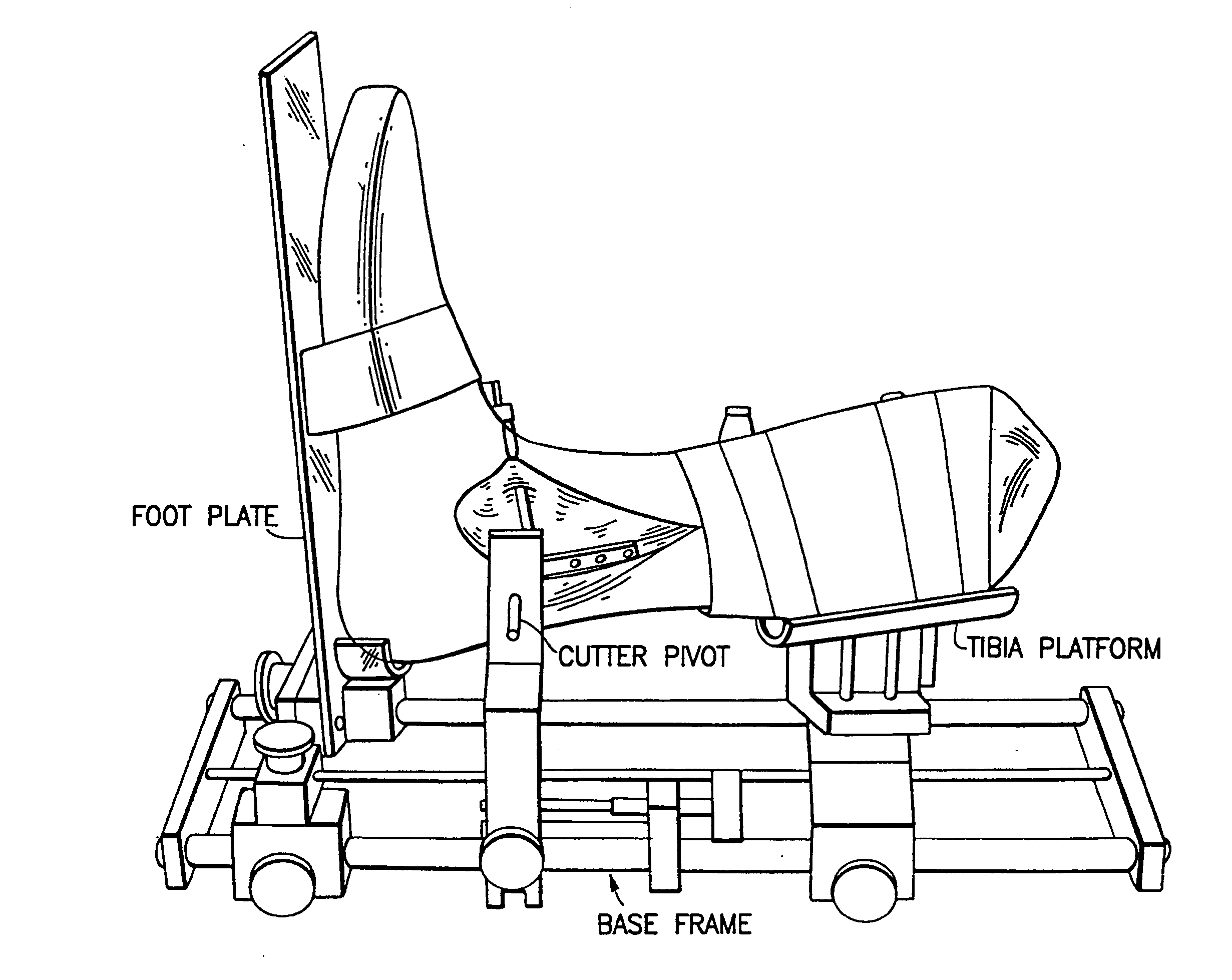
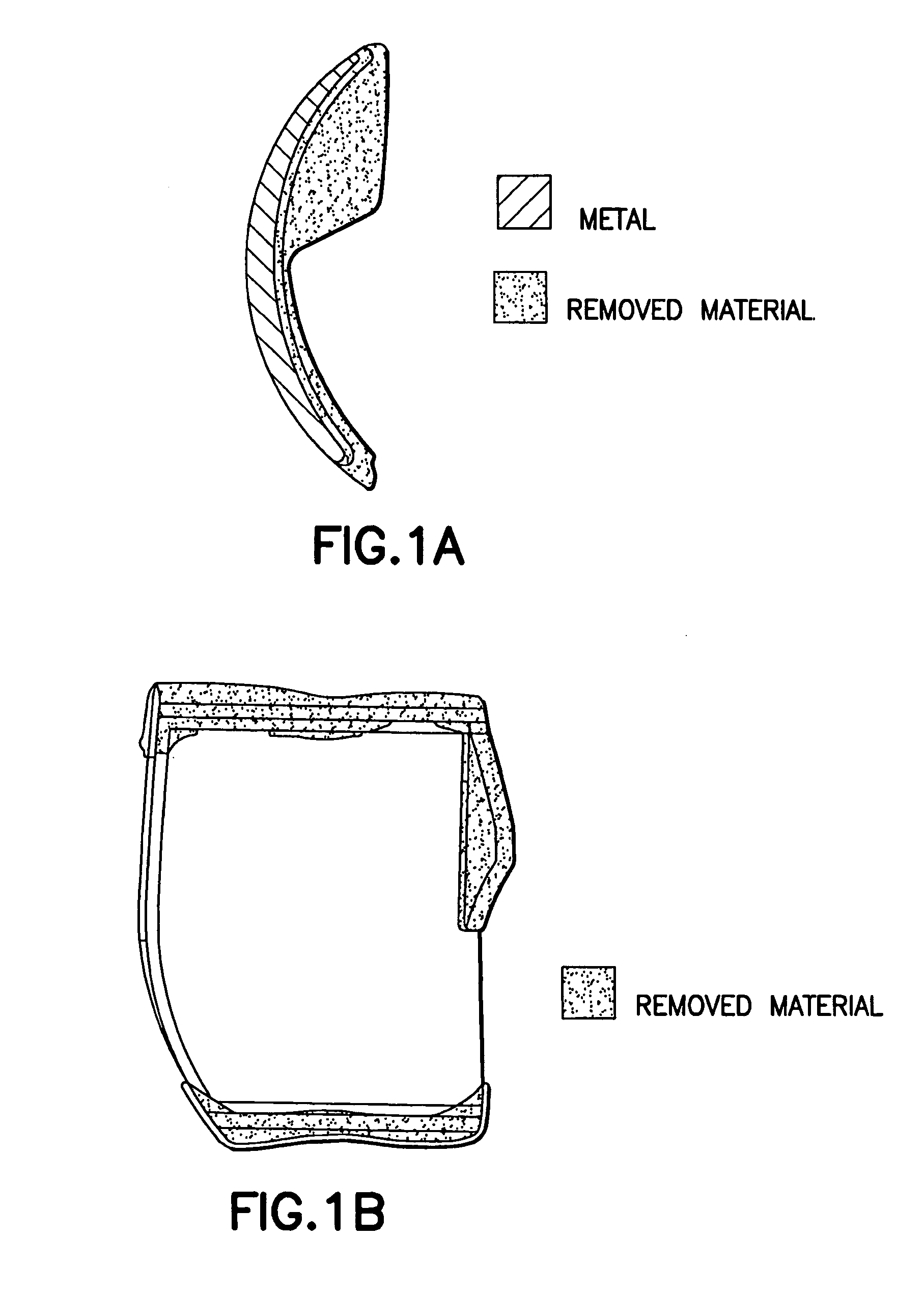
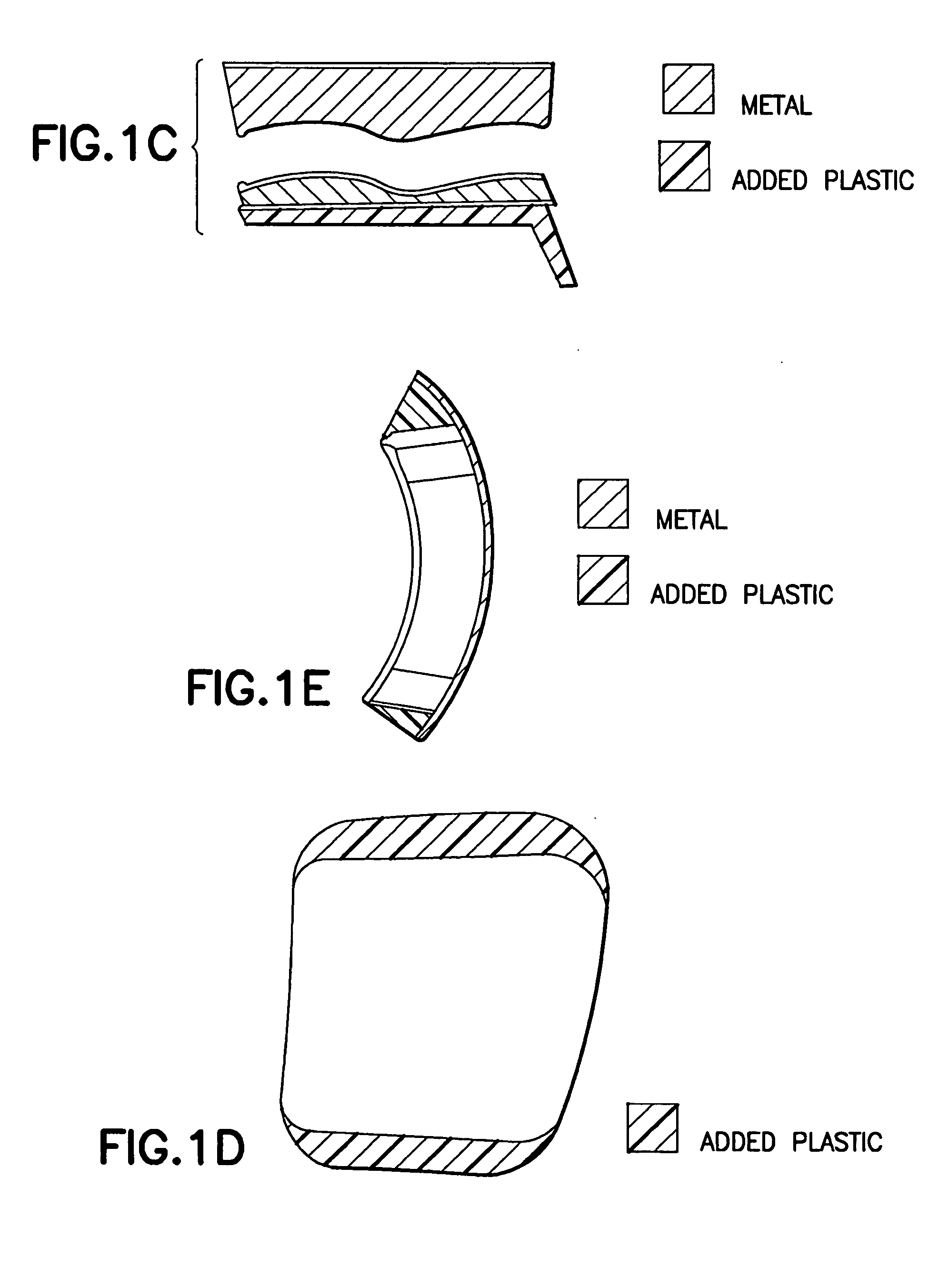
[0021] In one embodiment an ankle prosthesis according to the present invention minimizes edge loading by using bicondylar articular geometry which enhances varus / valgus stability while maintaining an appropriately central load distribution within the prosthesis. In this r...


PUM


Abstract

One embodiment of the present invention relates to an ankle prosthesis. Another embodiment of the present invention relates to a total ankle replacement prosthesis. Another embodiment of the present invention relates to an ankle replacement (partial or total) which is adapted, for example: (a) to treat arthritis of the ankle (e.g., ankle arthritis of any cause: after precious trauma; primary; malalignment induced; after hindfoot fusion; from recurrent ankle instability; rheumatoid or inflammatory arthritis; gout; local growth; dysplasia; growth plate arrest; avascular necrosis; hemophilia; distant septic event); (b) to revise a fused ankle; and / or (c) to treat trauma. The ankle replacement may be carried out by replacing one or more joint surfaces of an ankle joint. Another embodiment of the present invention relates to a method for inserting an ankle prosthesis.

Description

CROSS-REFERENCE TO RELATED APPLICATIONS [0001] This application claims the benefit under 35 U.S.C. 119(e) of U.S. Provisional Application Ser. No. 60 / 510,887, filed Oct. 14, 2003.FIELD OF THE INVENTION [0002] One embodiment of the present invention relates to an ankle prosthesis. [0003] Another embodiment of the present invention relates to a total ankle replacement prosthesis. [0004] Another embodiment of the present invention relates to an ankle replacement (partial or total) which is adapted, for example: (a) to treat arthritis of the ankle (e.g., ankle arthritis of any cause: after precious trauma; primary; malalignment induced; after hindfoot fusion; from recurrent ankle instability; rheumatoid or inflammatory arthritis; gout; local growth; dysplasia; growth plate arrest; avascular necrosis; hemophilia; distant septic event); (b) to revise a fused ankle; and / or (c) to treat trauma. The ankle replacement may be carried out by replacing one or more joint surfaces of an ankle join...

Claims


Application Information

Patent Timeline
Patent Type & Authority Applications(United States)
IPC IPC(8): A61B17/15A61B17/17A61B17/90A61FA61F2/42
CPCA61B17/15A61F2/4202A61B17/1739A61F2002/4207A61B2017/1775A61F2002/4205A61B17/1775
Inventor SALTZMAN, CHARLES L.BURSTEIN, ALBERT H.DELAND, JONATHAN T.
Owner UNIV OF IOWA RES FOUND
Learn More