
Lens barrel and image taking apparatus

Inactive Publication Date: 2005-08-25
FUJIFILM CORP +2
View PDF10 Cites 11 Cited by
  • Summary
  • Abstract
  • Description
  • Claims
  • Application Information

AI Technical Summary

Benefits of technology

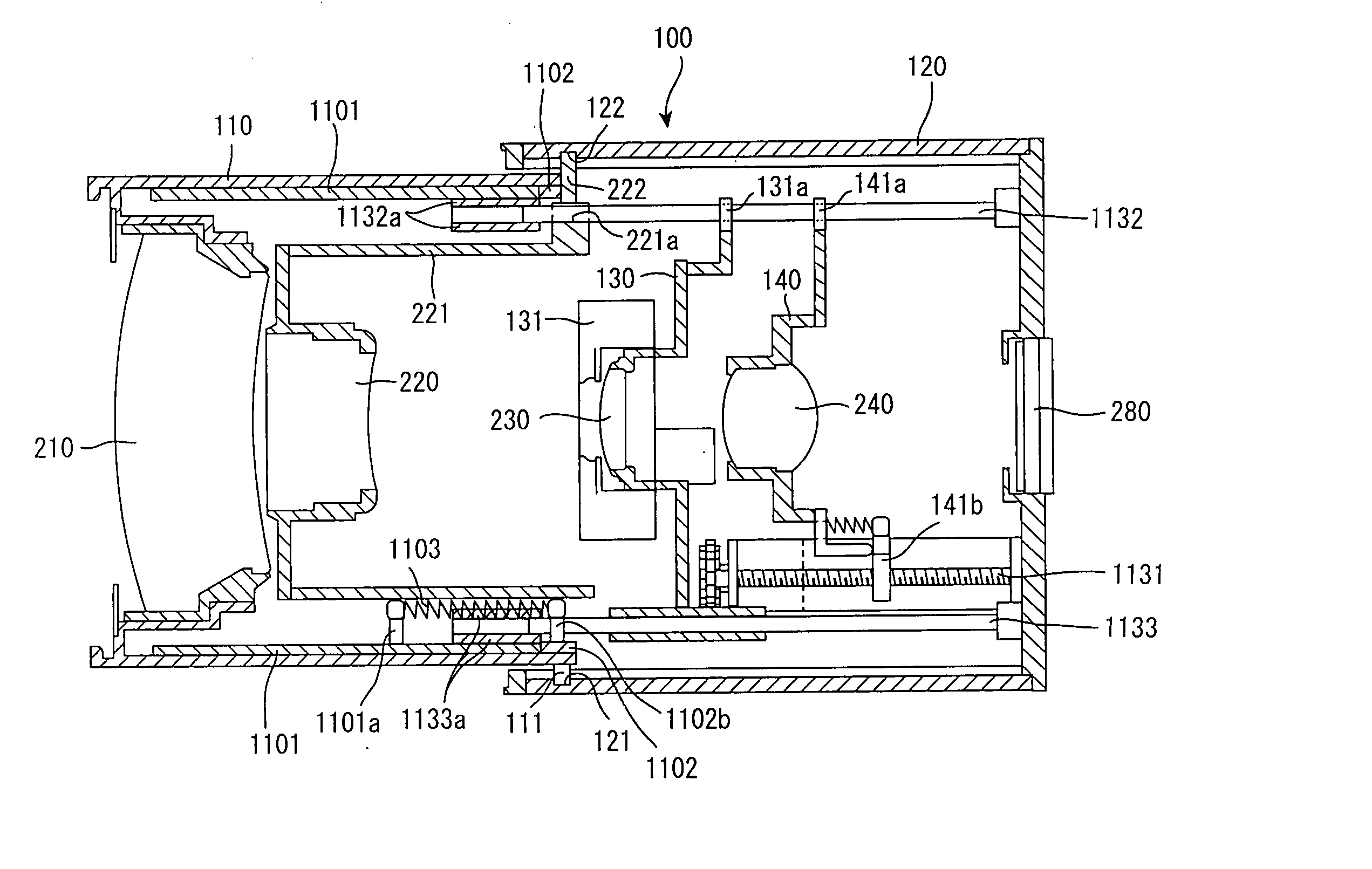
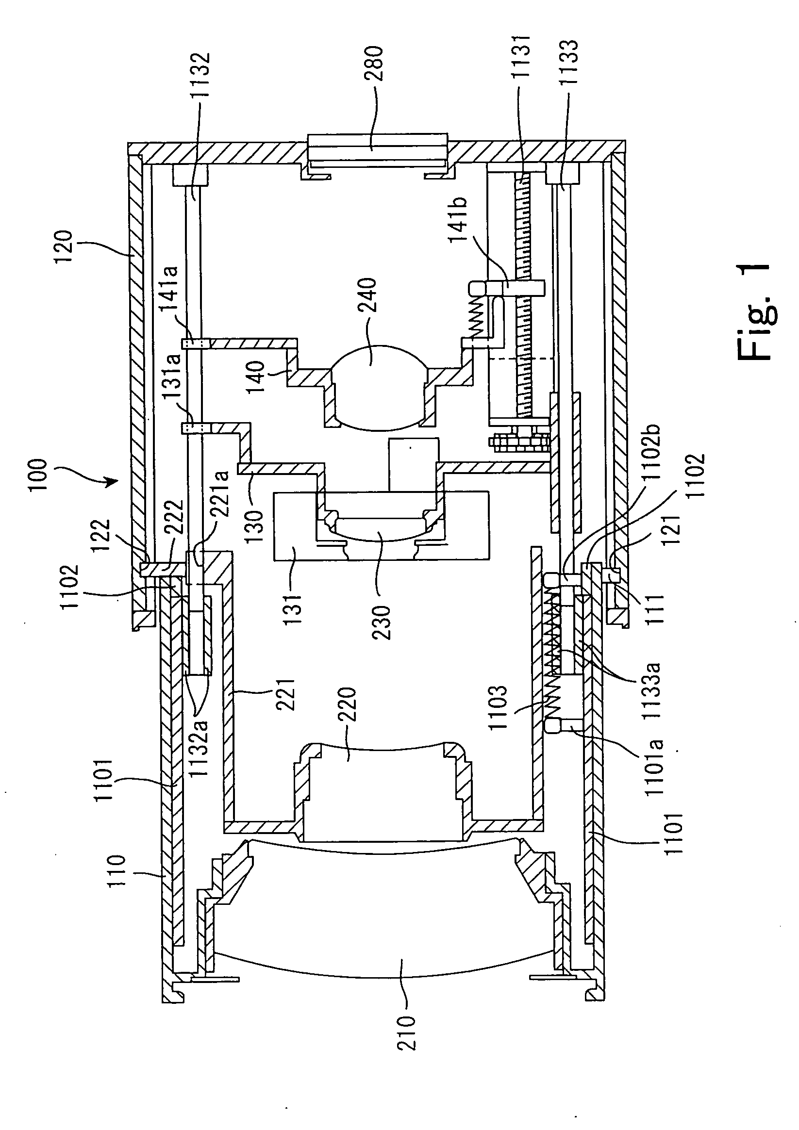
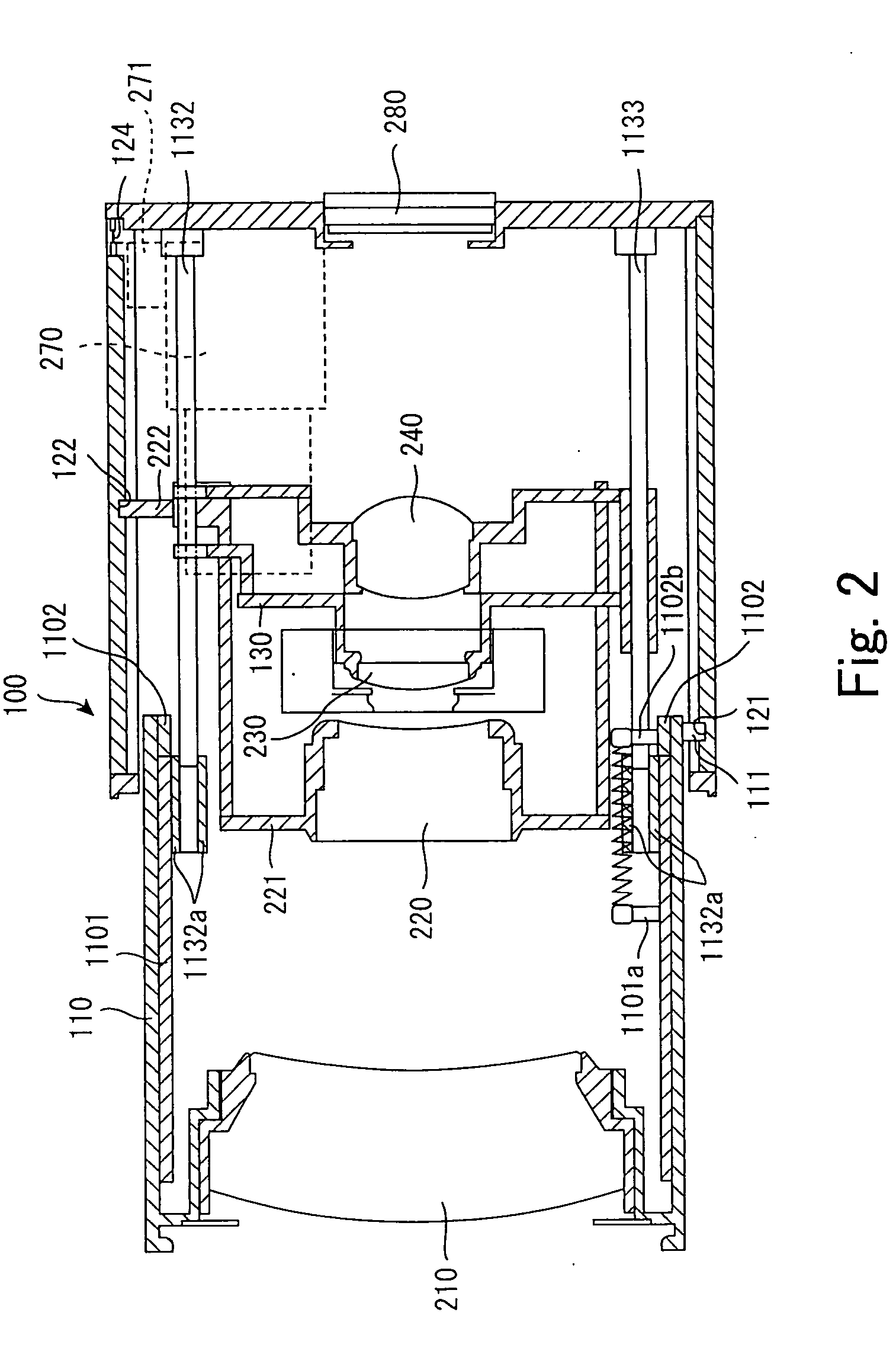
[0025] The present invention has been made in view of the above circumstances and provides a lens barrel in which the optical axes of lens groups can be readily aligned even if its length is shortened by dispensing with a guide rod long extending from a base which fixes an image pickup device, and an image taking apparatus into whose body the lens barrel is incorporated.
[0029] In the lens barrel according to the invention, out of the constituent groups of the zoom lens, all of the second lens group, third lens group and fourth lens group are fixed to the straight-ahead key member or supported by the straight-ahead key member to be able to advance or retract, and the first lens group is fixed to the front tube engaged with the straight-ahead key member to be able to advance or retract. Where all of the second lens group, third lens group and fourth lens group are mounted on the straight-ahead key member, the optical axes can be aligned with high precision, there can be realized a lens barrel in which the optical axes of the multiple lens groups can be easily aligned even if a reduction in length is attempted by dispensing with guide rods or the travel mechanism long extending from the base which fixes the image pickup device.
[0045] Where such an image pickup device is provided, a further enhancement in zoom ratio can be achieved by performing electronic zooming by using the image pickup device in addition to optical zooming.
[0046] As hitherto described, there are realized a lens barrel in which the optical axes of the multiple lens groups can be easily aligned even if a reduction in length is attempted by dispensing with guide rods or the travel mechanism long extending from the base which fixes the image pickup device, and an image taking apparatus whose body has the lens barrel incorporated into it.

Problems solved by technology

Accordingly, it is extremely difficult to adjust the optical axis with high precision and, if this technique is applied to a zoom lens of a four lens-group configuration, adjustment of the optical axis and keeping its accuracy will be extremely difficult, making it prohibitively difficult to extend this technique as it is to a four lens-group configuration.

Method used


Image

  • Lens barrel and image taking apparatus
  • Lens barrel and image taking apparatus
  • Lens barrel and image taking apparatus

Examples


Embodiment Construction

[0060] An embodiment of the present invention is described below.

[0061]FIGS. 5 and 6 are external perspective views of a digital camera, which is an embodiment of an image taking apparatus according to the present invention and which incorporates an embodiment of a lens barrel according to the invention.

[0062]FIG. 5 is an external view of a lens barrel 310 incorporated into this digital camera 300 when it is in a collapsed state, and FIG. 6 is an external view of that lens barrel 310 when it is in an extended state.

[0063] The lens barrel 310 of the digital camera 300 shown in FIGS. 5 and 6 has an image taking lens consisting of four lens groups built into it which is to be described afterwards. By moving a second lens group out of those four lens groups in the direction of the optical axis, the focal distance is adjusted, and by moving a fourth lens group as the focus lens in the direction of the optical axis, focusing is performed.

[0064] In the upper front part of the digital c...


PUM


Abstract

A lens barrel has its length which is reduced by dispensing with guide rods or a travel mechanism long extending from a base which fixes an image pickup device. The optical axes of multiple lens groups can be easily aligned. An image taking apparatus has its body which has the lens barrel incorporated into it. A second lens group, third lens group and, via the travel mechanism, a fourth lens group are supported by a straight-ahead key ring, and the straight-ahead key ring also supports a front tube holding the first lens group. A zoom motor and a focus motor are also supported by the straight-ahead key ring.

Description

BACKGROUND OF THE INVENTION [0001] 1. Field of the Invention [0002] The present invention relates to a lens barrel which holds a zoom lens consisting of multiple lens groups as well as to an image taking apparatus which is provided with the lens barrel and takes images by capturing light from a subject entering through the zoom lens held by the lens barrel. [0003] 2. Description of the Related Art [0004] Today, digital cameras are in rapidly expanding use, and they are required to provide ever higher image quality along with reductions in overall size and profile thickness. As a digital camera to meet these requirements, there is proposed a thin visiting card-size digital camera equipped with a lens barrel holding a zoom lens consisting of multiple lens groups (see non-patent literature 1, Internet URL http: / / www.business-ijp / sentan / jusyou / 2003 / pentax / ) and is already commercially available. This digital camera permits zooming with high image quality with an optical zoom while earli...

Claims


Application Information

Patent Timeline
IPC IPC(8): G02B7/02G02B7/04G02B7/10G02B15/14G03B17/12H04N5/225
CPCG02B15/14G02B7/102G02B15/144
Inventor OMIYA, AKIOSENBA, TAKEHIKOENDO, HIROSHI
Owner FUJIFILM CORP
Learn More