
Temperature sensor

a temperature sensor and temperature sensor technology, applied in the field of sensors, can solve the problems of increased cost, significant cost, and additional cost, and achieve the effects of high cost, enhanced design freedom of ceramic cooktops, and maximum operational reliability

Inactive Publication Date: 2005-08-25
REITER WERNER
View PDF11 Cites 15 Cited by
  • Summary
  • Abstract
  • Description
  • Claims
  • Application Information

AI Technical Summary

Benefits of technology

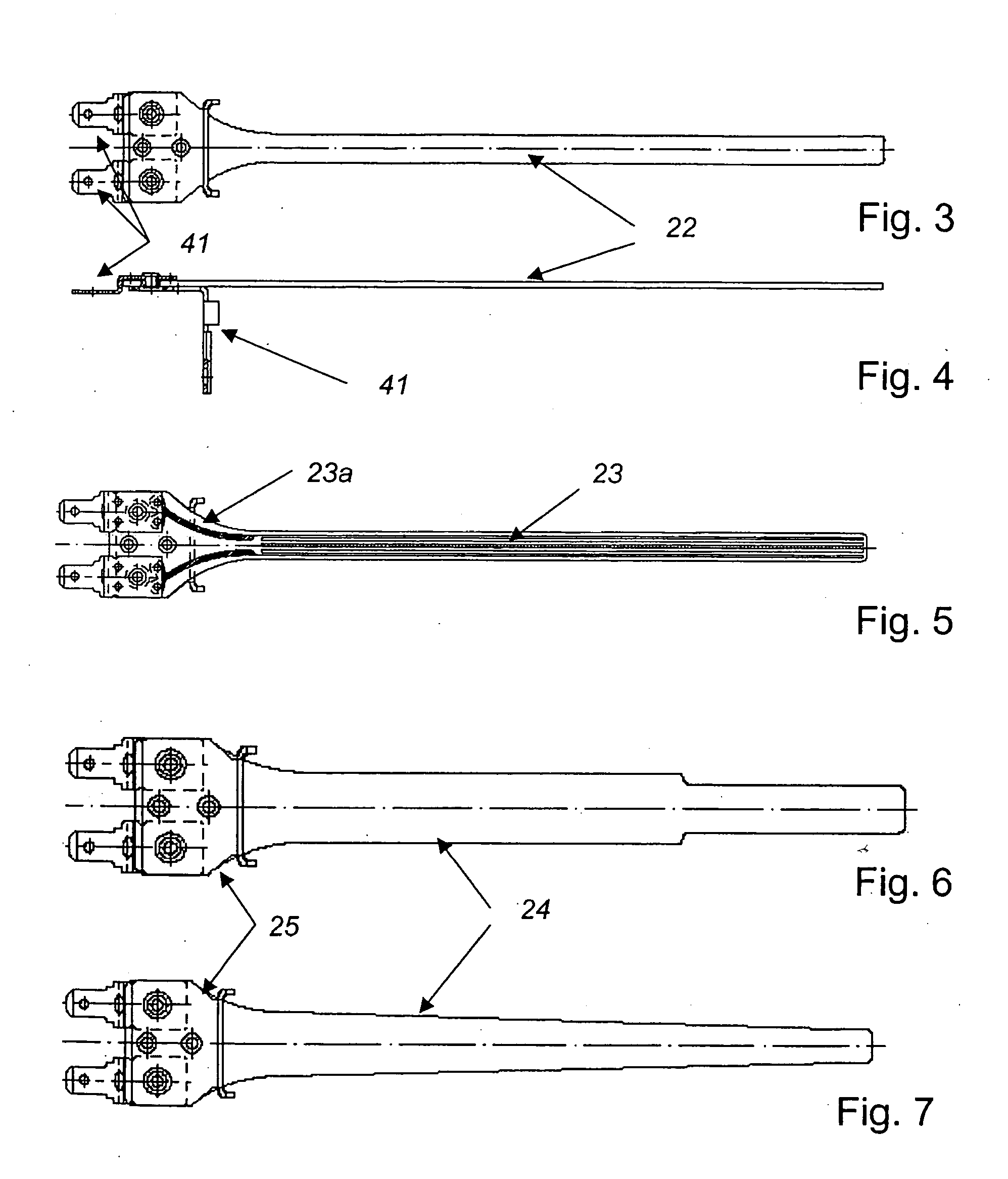
"The present invention relates to a temperature sensor for a ceramic cooktop that can measure the temperature of the heating area. The sensor includes a ceramic element and a temperature-dependent resistor web attached to the ceramic element. The resistor web has a larger cross-section in the region between the contact points, which reduces the influence of the temperature on the measurement. The ceramic element has a broadened region at the contact point, facing away from the heating area, to improve mechanical stability. The sensor can be calibrated automatically and cost-effectively in the installed state, ensuring maximum operational reliability of the ceramic cooktop. The sensor can also be used to detect and prevent excessive temperatures that could damage neighboring furniture. The computer unit can store temperature-time curves and calculate the current temperature at any point on the ceramic cooktop."

Problems solved by technology

However, the calibration of sensors requires a significant outlay and therefore causes significant costs.
For example, resistance sensors must be trimmed into some sort of shape, this trimming not only causing additional costs, but rather also impairing the quality of the sensor and partially determining the size of the sensor.
However, it cannot be conclusively inferred from the embodiment specified therein how the temperature detection criteria required for cooktops per se are technically achieved using the platinum resistance sensor specified.

Method used


Image

  • Temperature sensor
  • Temperature sensor
  • Temperature sensor

Examples


Embodiment Construction

[0031] Throughout all the Figures, same or corresponding elements are generally indicated by same reference numerals. These depicted embodiments are to be understood as illustrative of the invention and not as limiting in any way. It should also be understood that the drawings are not necessarily to scale and that the embodiments are sometimes illustrated by graphic symbols, phantom lines, diagrammatic representations and fragmentary views. In certain instances, details which are not necessary for an understanding of the present invention or which render other details difficult to perceive may have been omitted.

[0032] Resistance sensors are usable very cost-effectively. Platinum resistance sensors in particular are distinguished by a low temporal drift. The calculation method for determining R0 is distinguished by special simplicity and may be executed by a simple and therefore cost-effective computer unit.

[0033] In a further embodiment of the present invention, it is advantageous...


PUM

PropertyMeasurementUnit
lengthaaaaaaaaaa
temperatureaaaaaaaaaa
temperature T0aaaaaaaaaa

Abstract

A sensor positioned between a heat source and a heating area in parallel relationship to the heating area, for determining a mean value of the temperature of the heating area, includes a ceramic element, and a temperature-dependent resistor web attached to the ceramic element and confronting the heating area at a distance thereto. The resistor web has a length of at least 200 mm, and is electrically contacted at a contact point outside a region in which the temperature is to be ascertained.

Description

CROSS-REFERENCES TO RELATED APPLICATIONS [0001] This application claims the priority of European Patent Application, Serial No. 04004153.5, filed Feb. 24, 2004, pursuant to 35 U.S.C. 119(a)-(d). BACKGROUND OF THE INVENTION [0002] The present invention relates to a sensor for determining the mean value of the temperature of a heating area heated by a heat source, such as a glass ceramic hot plate, which is positioned between the heat source and the heating area and parallel thereto, the sensor comprising a ceramic element and a temperature-dependent resistor web attached to the ceramic body and the resistor web being positioned facing toward the heating area and at a distance thereto. [0003] In typical electric stoves, particularly having a ceramic cooktop, one electromechanical protective temperature limiter is provided per heater to limit it to the maximum temperature. If the cooking platform is controlled using an electronic system, a substitution of the mechanical temperature lim...

Claims


Application Information

Patent Timeline
Patent Type & Authority Applications(United States)
IPC IPC(8): G01K15/00
CPCG01K15/00
Inventor REITER, WERNERMARX, CHRISTIAN
Owner REITER WERNER
Learn More