
Integrated Shale Shaker and Dryer

a technology of shale shaker and dryer, which is applied in the direction of gas current separation, solid separation, chemistry apparatus and processes, etc., can solve the problems of viscosity and gel problems, increase the wear of mud pumps and other mechanical equipment used for drilling, and the shaker itself occupies a rather large area, so as to increase the flow rate of drilling mud

Inactive Publication Date: 2005-08-25
HUTCHISON HAYES INT
View PDF36 Cites 47 Cited by
  • Summary
  • Abstract
  • Description
  • Claims
  • Application Information

AI Technical Summary

Benefits of technology

[0004] At the top of the well, the solids-laden mud is introduced to a shale shaker, a device which typically has a series of screens arranged in tiered or flat disposition with respect to each other. The screens catch and remove solids from the mud as the mud passes through them. If drilled solids are not removed from the mud used during the drilling operation, recirculation of the drilled solids can create viscosity and gel problems in the mud, as well as increasing wear in mud pumps and other mechanical equipment used for drilling.
[0009] The present invention provides an integrated, transportable system including a multi-part shale shaker, preferably formed of six screens vibrated by at least one electric vibrator, and preferably four such vibrators. Solids are screend from drilling mud flowing onto the screens, and directed into a trough wherein is located a screw conveyor or augur. A pressure differential is developed across the screens to increase the flow rate of drilling mud through the screens.

Problems solved by technology

If drilled solids are not removed from the mud used during the drilling operation, recirculation of the drilled solids can create viscosity and gel problems in the mud, as well as increasing wear in mud pumps and other mechanical equipment used for drilling.
The frame of the vibrating screen is resiliently suspended or mounted upon a support and is caused to vibrate by a vibrating mechanism, e.g. an unbalanced weight on a rotating shaft connected to the frame.
A major problem with the art just described is that the cuttings laden drilling mud is introduced to the top surfaces of the shale shaker screen and allowed to flow downward through the screen by gravity alone.
Another major problem with the art is that the shale shaker itself occupies a rather large area, and area is a precious commodity on offshore drilling rigs.
Furthermore, the solids must be transported away from the shale shaker to remove more of the drilling mud from the cuttings, and the transport system and the further treatment systems occupy even more of the area of the drilling rig.

Method used


Image

  • Integrated Shale Shaker and Dryer
  • Integrated Shale Shaker and Dryer
  • Integrated Shale Shaker and Dryer

Examples


Embodiment Construction

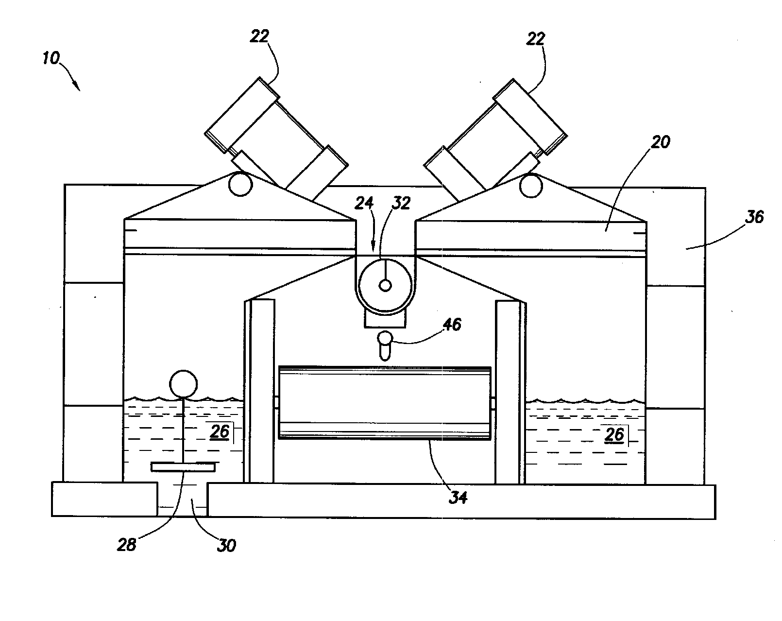
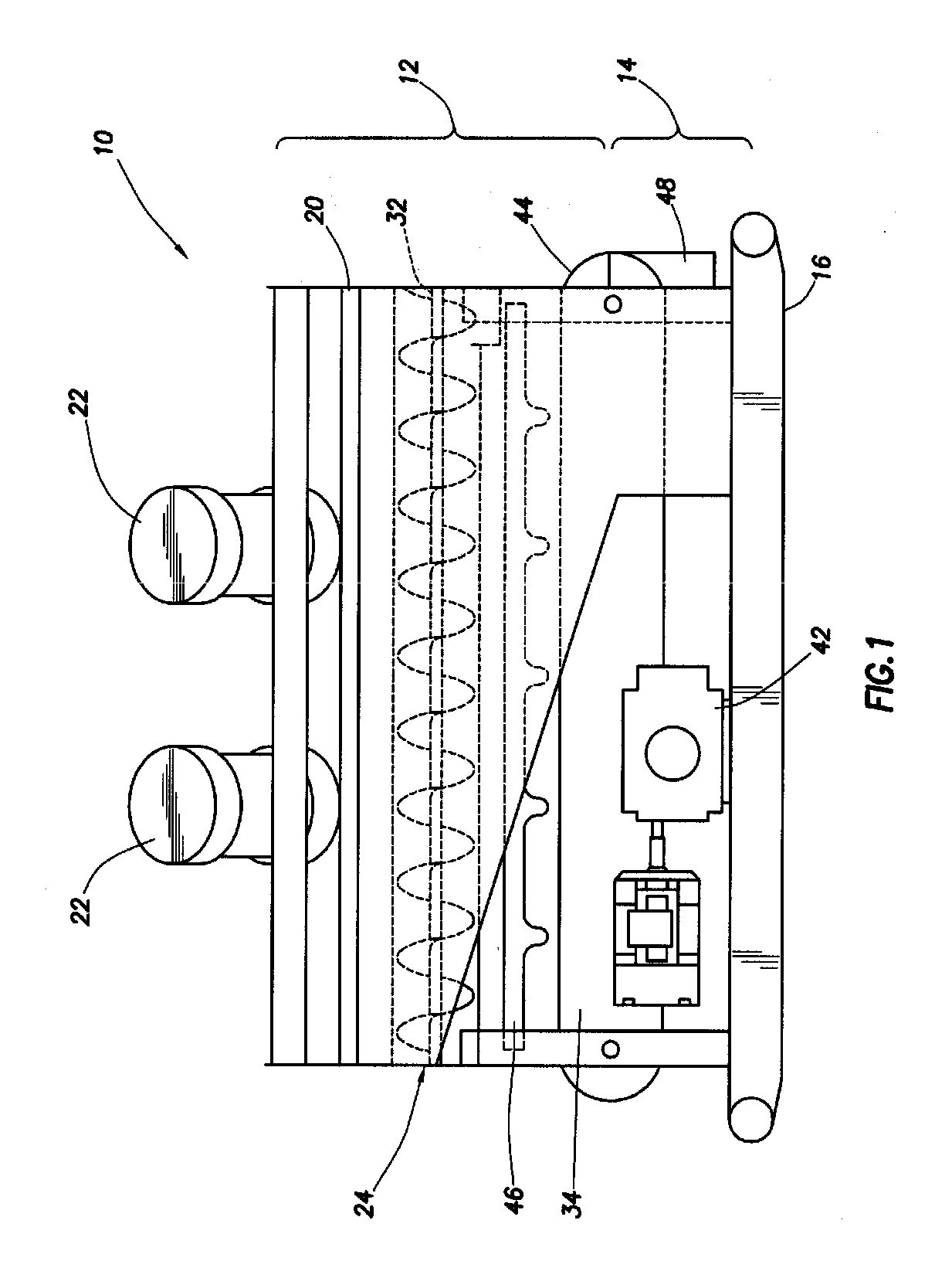
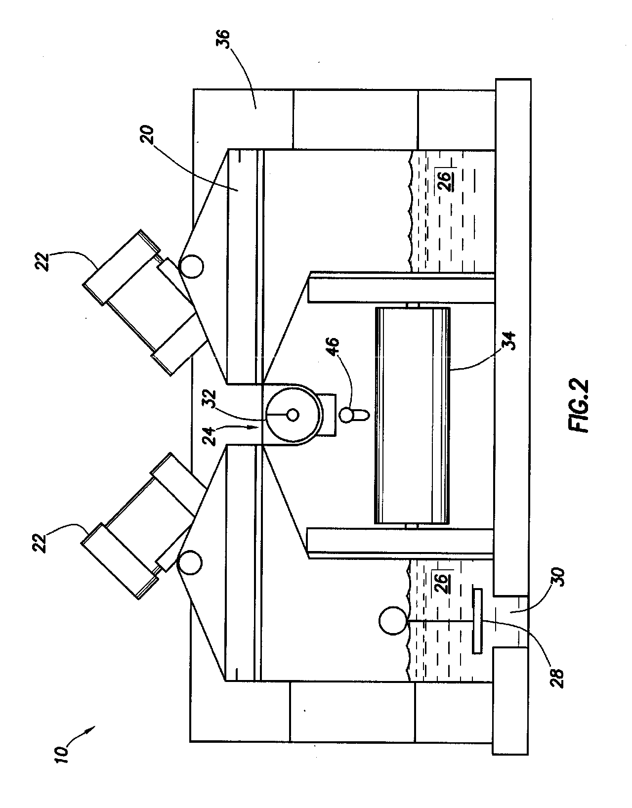
[0016]FIGS. 1, 2, and 3 show an integrated system 10 of this invention. The system 10 comprises primarily an upper section 12 defining a new shale shaker and a lower section 14 defining a new cuttings treatment system, all mounted to a pallet or skid 16 for the easy transportation of the entire system 10. The feature of the present invention provides an integrated, portable solids cleaning system.

[0017] The system includes a plurality of vibrating shaker screens 20, in a preferred embodiment six of such screens. The screens 20 are vibrated by at least one electric vibrator 22, preferably four such vibrators as shown in FIG. 3. The vibratos impart vibratory motion to the screens in a manner well known in the art as drilling mud, carrying cuttings, flows down through the screens. Solids larger than the mesh size of the screens are caught on top of the screens, and the vibratory action moves the solids across the screens down into a center trough 24. Liquid drilling mud, with some sma...


PUM


Abstract

An integrated, transportable cuttings treatment system includes a multi-part shale shaker, preferably formed of six screens vibrated by at least one electric vibrator, and preferably four such vibrators. Solids are screen from drilling mud flowing onto the screens, and directed into a trough wherein is located a screw conveyor or augur. A pressure differential is developed across the screens to increase the flow rate of drilling mud through the screens.

Description

DESCRIPTION [0001] This application claims the benefit of provisional U.S. Patent application Ser. No. 60 / 543,583 filed Feb. 11, 2004.FIELD OF THE INVENTION [0002] The present invention relates generally to the field of shale shakers commonly used in the treatment of drilling mud and, more particularly, to an integrated system including a shale shaker and a dryer to treat the cuttings separated by the shale shaker. BACKGROUND OF THE INVENTION [0003] As described in U.S. Pat. No. 5,392,925 to Seyffert, the need for controlling the solids content in drilling mud is well known in the art. Drilling mud, typically a mixture of clay, water, and various additives, is pumped down through the center of a drill string into a well. At the bottom of the drill string, the drilling mud exits through holes or jets in a drill bit. The mud picks up cuttings and other solids from the well and carries them upwardly away from the bit and out of the well in the annulus between the well walls and the dri...

Claims


Application Information

Patent Timeline
Patent Type & Authority Applications(United States)
IPC IPC(8): B07B1/46B07B4/08B07B13/16
CPCB07B1/46B07B2230/01B07B13/16B07B4/08
Inventor HENSLEY, GARY L.HILPERT, LEE
Owner HUTCHISON HAYES INT
Learn More