Fuel delivery module assembly

a technology of fuel delivery module and assembly, which is applied in the direction of machine/engine, combustion air/fuel-air treatment, and separation processes, etc., can solve the problems of more difficult introduction of the assembly into the fuel tank, and achieve the effect of reducing the number of apertures, minimizing the risk of emissions permeation loss, and reducing costs

Active Publication Date: 2005-08-25
FORD GLOBAL TECH LLC
View PDF35 Cites 4 Cited by
  • Summary
  • Abstract
  • Description
  • Claims
  • Application Information

AI Technical Summary

Benefits of technology

[0024] The fuel delivery module assembly may also include a level sensing device for use in determining a level of fuel within a fuel tank. The level sensing device is preferably a pivotal float arm which includes means for indicating an angle of the float arm. It is desirable to have a level sensing device within the fuel tank so that the fuel level within the fuel tank can be monitored. It is preferable to have the device mounted on the fuel delivery module assembly so that it can be inserted into the fuel tank via the same aperture. This reduces the number of apertures in the fuel tank thereby minimizing the risk of emissions permeation losses via seals around the apertures.
[0025] It is preferred that the level sensing device is attached to the distal component as this provides some flexibility regarding the positioning of the level sensing device relative to the aperture in the fuel tank. Since the distal component is displaced away from the central axis of the aperture during fuel tank construction, the direction of the displacement can be used to position the level sensing device advantageously. It is often preferable to have the level sensing device located centrally within a fuel tank.
[0026] The fuel delivery module assembly may further comprise an extendable rod extending between the flange and the distal component. This rod provides extra stability to the sliding relationship between the fuel delivery module and the emissions canister. If such a rod is used, it is preferred that the distal component is resiliently biased away from the flange by a compression spring surrounding at least part of the extendable rod. This also assists in maintaining the distal component in a stable position within the fuel tank.
[0027] By providing such an assembly, a standardized fuel tank can be used in a vehicle for a range of engine sizes. The fuel tank can have an aperture that is sized to permit a standardized fuel delivery module to enter the fuel tank and an emissions canister of a suitable size for the engine size and vehicle use can be attached to the fuel delivery module without the need for the aperture to be enlarged or otherwise altered. It is desirable to have standard car parts across entire car model ranges as this reduces costs. The size of the fuel pump and the size of the emissions canister required may depend on the size of the engine of a car. Using the present invention, the size of these two components can be readily altered without affecting the size of the fuel delivery module or the size of the aperture required in the fuel tank. The aperture and fuel delivery module can both therefore remain a standard size, thereby reducing the overall cost of the car.
[0028] It is preferred that components forming the sliding joint will be capable of being snap-fitted together so that alternative sizes of components can be easily mounted onto one another. In particular, alternative sizes of emissions canisters may be easily mounted onto a universal fuel delivery module. In addition, as the emissions canister and the fuel delivery module sit side by side within the vehicle fuel tank such that the reservoir and emissions canister overlap parallel with the slide axis, the two components can be inserted into a relatively shallow fuel tank.

Problems solved by technology

However, it is likely to be more difficult to introduce the assembly into the fuel tank when the two components overlap.

Method used


Image

  • Fuel delivery module assembly
  • Fuel delivery module assembly
  • Fuel delivery module assembly

Examples


Embodiment Construction

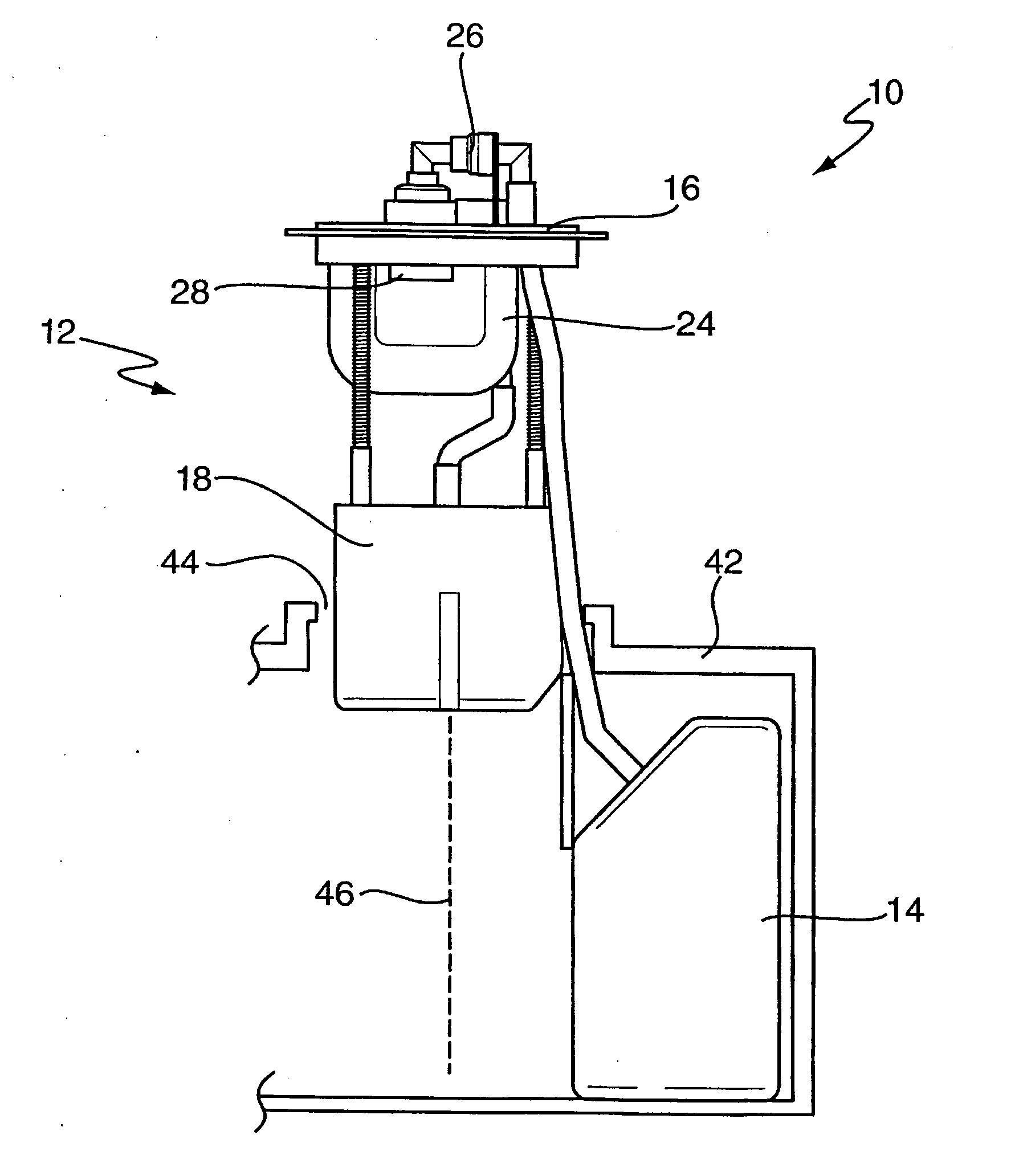
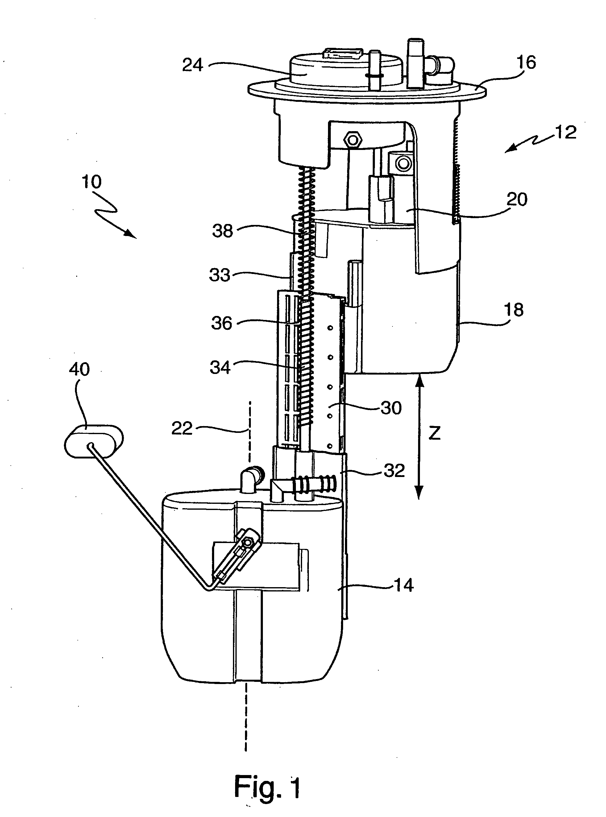
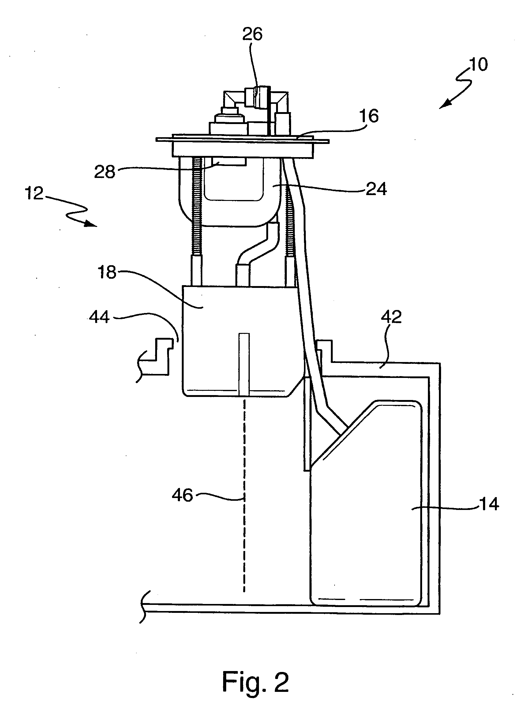
[0036]FIG. 1 is a schematic diagram of a fuel delivery module assembly 10 for a vehicle in an installation position. The fuel delivery module assembly 10 comprises a fuel delivery module 12 for supplying fuel from a fuel tank, a flange 16 for attachment to a fuel tank and an emissions canister 14 for controlling evaporative emissions from a fuel tank. The fuel delivery module 12 comprises a reservoir 18 for retaining fuel and a fuel pump 20 for supplying fuel from the reservoir 18. The flange 16 is coupled to a proximal component, in this case the fuel delivery module 12, which is coupled to a distal component, in this case the emissions canister 14.

[0037] The emissions canister 14 is coupled to the fuel delivery module 12 in a sliding relationship and is arranged such that the emissions canister 14 can be displaced relative to the fuel delivery module 12 away from or towards the flange 16 along a slide axis 22. The fuel delivery module assembly 10 further comprises an integrated l...


PUM

PropertyMeasurementUnit
permeationaaaaaaaaaa
permeation lossesaaaaaaaaaa
widthaaaaaaaaaa

Abstract

A fuel delivery module assembly for a vehicle which includes a fuel delivery module for supplying fuel from a fuel tank, a flange for attachment to a fuel tank and an emissions canister for controlling evaporative emissions. The fuel delivery module includes a reservoir for retaining fuel and a fuel pump for supplying fuel from the reservoir. The emissions canister is coupled to the fuel delivery module in a sliding relationship and is arranged such that the emissions canister can be displaced along a slide axis relative to the fuel delivery module between an installed position, in which the reservoir and emissions canister overlap parallel with the slide axis, and an installation position, in which the reservoir and emissions canister substantially do not overlap parallel with the slide axis. The invention also provides a fuel tank assembly comprising such a fuel delivery module assembly and to a method of positioning such a fuel delivery module assembly within a fuel tank.

Description

CROSS-REFERENCE TO RELATED APPLICATIONS [0001] This application claims, under 35 U.S.C.§119(e), the benefit of U.S. Provisional Patent Application Ser. No. 60 / 540,244 filed on Jan. 29, 2004.BACKGROUND OF THE INVENTION [0002] The present invention relates to a fuel delivery module assembly comprising both a fuel delivery module for supplying fuel and an emissions canister for controlling evaporative emissions, to a fuel tank assembly comprising such a fuel delivery module assembly and to a method of positioning the fuel delivery module assembly within a fuel tank. [0003] It is well known to provide a fuel tank in a vehicle to store fuel which is to be used by an internal combustion engine of the vehicle. In order to comply with emissions regulations, vehicles may now include a vapor control system to reduce evaporative emissions from the fuel tank. Such systems typically include an emissions canister, such as a carbon canister, which is used to trap evaporative emissions from the fue...

Claims


Application Information

Patent Timeline
Patent Type & Authority Applications(United States)
IPC IPC(8): B60K15/035B65D88/64F02M37/04F02M37/10F02M37/20F02M37/22
CPCB60K15/03504B60K2015/03557F02M37/22F02M37/20F02M37/103Y10T137/86035F02M37/32B60K15/077F02M37/00
Inventor HORVATH, ZOLTANBIEGELBAUER, PALVITALIS, TAMASBALAZS, KAROLYSOOS, MIHALYNYESTE, VIKTORKARIKO, ZSOLT
Owner FORD GLOBAL TECH LLC
Why Eureka
Try Eureka