
Hand controller and wrist device

Inactive Publication Date: 2005-08-25
UNIVERSITY OF MANITOBA
View PDF31 Cites 117 Cited by
  • Summary
  • Abstract
  • Description
  • Claims
  • Application Information

AI Technical Summary

Benefits of technology

[0025] It is an object of the present invention to provide a telerobotic system that may be used for diagnosis and / or other operations to be performed by a doctor or physician on a remote patient. Preferred applications of the invention are in the areas of Distance Abdominal Palpation (DAP) and Distance Ultrasound Diagnosis (DUD). The DAP-DUD system will primarily be used in situations wherein a bedside expert is not available. This allows patients who would normally be transferred to the location of the specialist, to be examined by the specialist without having to travel. Thus, the services and information will be delivered to individuals in many cases without leaving their own communities.
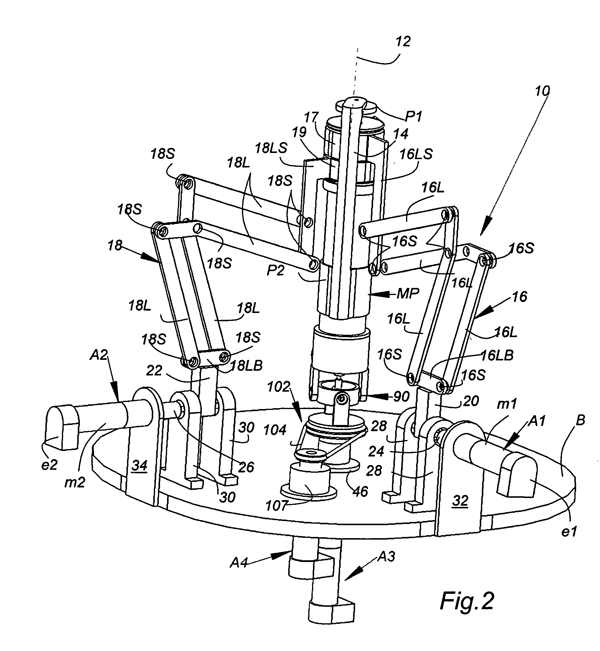
[0034] The power from each actuator is preferably transmitted to the driven axis by cables allowing the mechanism to be backdrivable. This not only allows easy measurements of the output force at the actuator sides, but also allows the probe to be passively pushed back by the patient in emergency circumstances. The mechanism exhibits a singular free, low friction, zero backlash, compact, rigid motion with a high-sustained output force. Broadly, the present invention relates to a hand controller or wrist device comprising a base and a moveable portion moveable relative to said base, said moveable portion having a main longitudinal axis and an end point, a pair of pantographs each formed by a plurality of pivotably interconnected links arranged for pivotal movement in a plane,

Problems solved by technology

For Example, accurate assessment of abdomen and interpretation of abdominal pain are difficult, particularly for the inexperienced clinician or nurse.
Errors and uncertainty can lead to delays in diagnosis and even death, as in appendicitis.
Although there is considerable interest and research in palpation technique in telehealth applications, currently there is no system equipped with kinematically similar configurations hand controller and robotic wrist that permits distant clinical palpation.
This includes abdominal examination as well as ultrasound diagnosis, which require expert assessment and are a frequent cause of patient transfer.
Additional extra degrees of freedom to these devices will unusually enlarge them or will require the actuators not to be grounded (i.e., become non-floating).
The use of non-symmetrical pantographs, however, works against the uniformity requirement [see paper by Hayward, V.
(1995), “Toward a seven axis haptic device”, proceedings IEEE International Conference on Intelligent Robots and Systems], which may degrade the performance of the device.
The yokes can be heavy, need precision machining and usually exhibit backlash.
The actuators in this device, however, are floating (i.e., they are placed at the moving joints) making it bulky and heavy.
The device is not only big, but also cannot provide the required motion for ultrasound diagnosis.
Available circular guides are bulky, heavy and difficult to be machined precisely.
Thus, it is not easy to install this device on the implement of a manipulator.
Accurate palpating of the probe along the roll axis, however, can only be made by the rotation of the entire parallelogram linkage about two perpendicular axes of rotation, and translation of the entire robot over a table.
Although the system is counterbalanced and backdrivable, motors are non-floating and the inertial effect of the system is not negligible.
As such the workspace is limited.
As a result, the conical workspace is limited.
The system appears to be bulky with limited workspace.
Furthermore, the device entirely embraces the patient and there is no reasonable access to the patient in emergency cases.
Also, it does not appear to be backdrivable due to the use of semi circular spur gears moved by small pinions.

Method used


Image

  • Hand controller and wrist device
  • Hand controller and wrist device
  • Hand controller and wrist device

Examples


Embodiment Construction

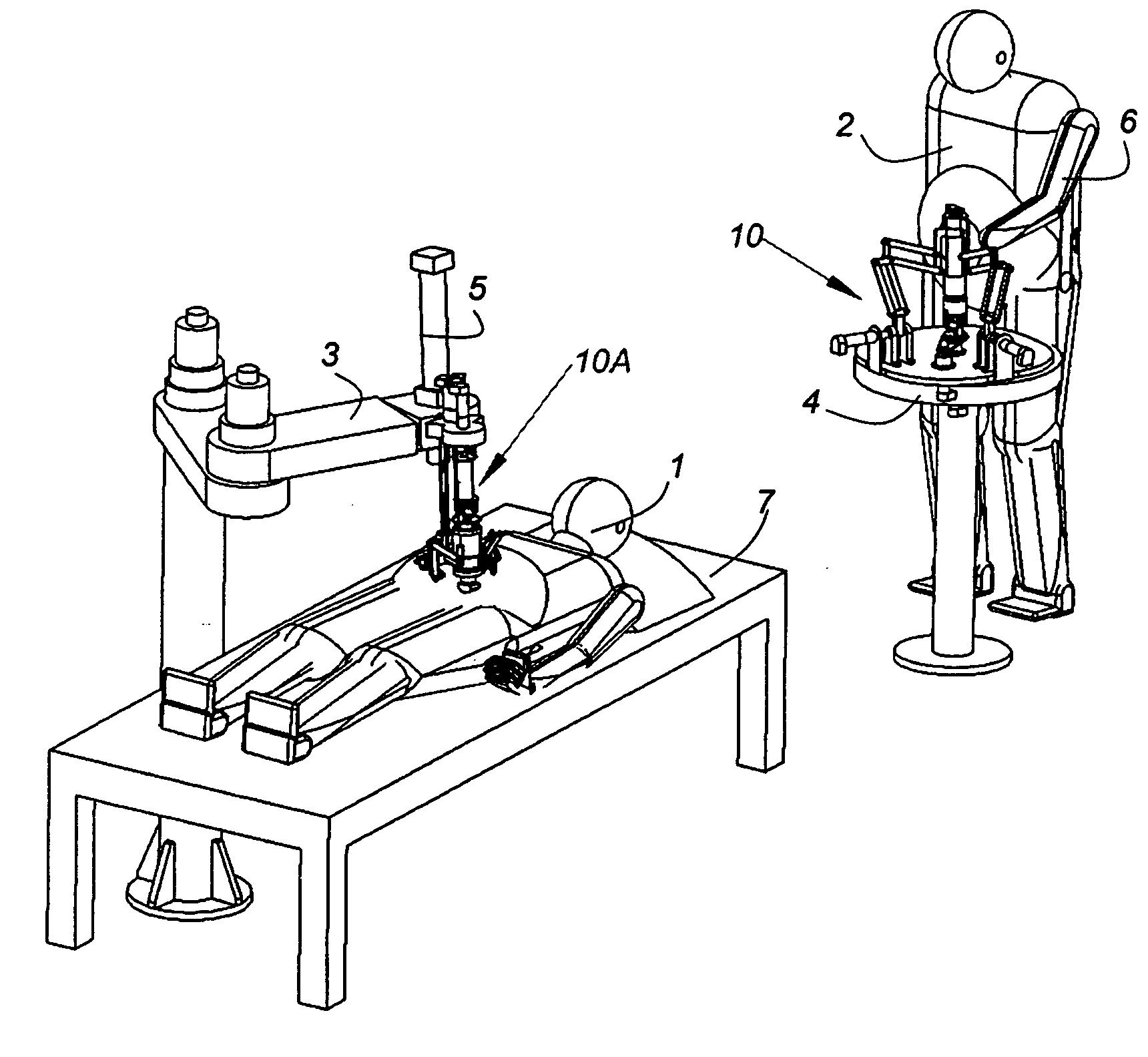
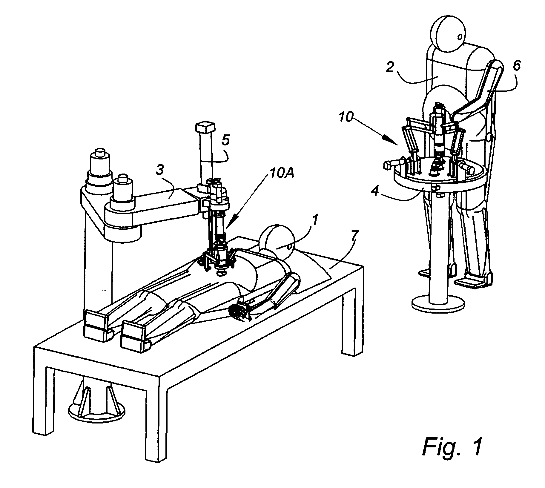
[0083] The present invention has many applications including those in the area of telerobotic and ultrasound / palpation procedures for which it is particularly adapted. As indicated in FIG. 1 the patient 1 is positioned on an examining table 7 at a location remote from the expert (physician) 2 who maneuvers the haptic or controller 10 mounted on a suitable table or base 4. In the illustrated arrangement the physician is showing using only one arm 6, but it will be apparent that either arm or both arms may be used. The controller 10 is held by a clinical expert and provides three or four degrees of freedom for orienting and positioning the wrist 10A which is mounted on a platform 5 with prismatic motion which is positioned by a stand 3 in overlying relationship to the patient 1 lying on table 7 at the location remote from the expert 2. The hand controller 10 reflects the sensed forces applied against of from the patient 1 to the physician's 2 hand i.e. the hand controller is provided ...


PUM


Abstract

A compact four degrees of freedom parallel mechanism suitable for use as a hand control or wrist is provided that has backdrivability, is singularity free and has a large workspace and a large force reflecting capability. The structure is light but rigid, and the electric actuators are all placed on the ground or base and provide independent control of each degree of freedom. Each degree of freedom is connected to an actuator either directly or through a cable drive system. The first two degrees of freedom are created by two identical pantographs pivoted together on pivoted joints to define a hemispherical motion of an object (end point) about a center point (hemisphere center). The third and fourth degrees of freedom represent rotation and sliding motions of the object around and along the radius of the created hemisphere, respectively. The axes of these latter degrees of freedom are concentric, and these axes intersect with the axis of the pantographs pivoted joints at the hemispheric center.

Description

FIELD OF INVENTION [0001] The present invention relates to a three or four Degree of Freedom (DoF) structure that may be used as a hand controller or haptic to be manipulated (preferably with force feedback) and / or a wrist structure the movement of which is to be controlled. BACKGROUND OF THE PRESENT INVENTION [0002] The concept of remote control in the medical field for diagnosis and or other operations to be performed by a Doctor on a remote patient is gaining more and more acceptance as it may be used to overcome serious problems of availability particularly in areas of low population insufficient to support locally a doctor having specific expertise. For Example, accurate assessment of abdomen and interpretation of abdominal pain are difficult, particularly for the inexperienced clinician or nurse. Errors and uncertainty can lead to delays in diagnosis and even death, as in appendicitis. These difficulties are amplified for remote patients who may have less timely and unequal ac...

Claims


Application Information

Patent Timeline
IPC IPC(8): A61B8/00A61B19/00B25J17/02G05G5/03G05G9/047
CPCA61B8/00Y10T74/20372A61B8/54A61B19/22A61B2019/2223A61B2019/223A61B2019/2234A61B2019/2242A61B2019/2246A61B2019/265B25J17/0266G05G5/03G05G9/047G05G2009/04777G05G2009/04781Y10T74/20305Y10T74/20201A61B8/4218A61B2034/715A61B2090/506A61B34/70A61B34/71A61B34/37A61B34/35A61B2034/305
Inventor NAJAFI, FARSHIDSEPEHRI, NARIMAN
Owner UNIVERSITY OF MANITOBA
Learn More