
Power converter and system using the same

a power converter and power technology, applied in the direction of dc-ac conversion without reversal, cross-talk/noise/interference reduction, circuit electrical arrangement, etc., can solve the problems of increasing the frequency of emi (electromagnetic interference) noise generated by the system using the power converter, affecting the operation of the system, and causing electromagnetic hazards. to be able to generate, the effect of reducing the frequency of emi noise and preventing the maintenan

Inactive Publication Date: 2005-08-11
KEIO UNIV
View PDF5 Cites 16 Cited by
  • Summary
  • Abstract
  • Description
  • Claims
  • Application Information

AI Technical Summary

Benefits of technology

[0019] The invention is carried out in view of the above-described situation, and has an object thereof to reduce an EMI noise generated from a power converter controlled by switching operation by a simple constitution.
[0021] According to the invention, not only a conducting EMI noise but also a radiating EMI noise can simultaneously be restrained. Further, an EMI noise restraining effect is incorporated from a product design stage and therefore, an extra noise countermeasure part is dispensed with and even in a series of products, a uniform noise restraining effect can be achieved for all of the products.
[0024] According to the invention, a parameter can be corrected to be proper easily in maintenance and therefore, the uniform noise restraining effect is achieved until ultimate life of the product. Further, since only the impedance is inserted therebetween, an existing system can also be dealt with easily without being influenced by a constructing state or condition.
[0026] According to the invention, rise of a potential of an element constituting the system (for example, a frame or the like) can be avoided and therefore, the EMI noise can be restrained while preventing electric shock.

Problems solved by technology

A power converter controlled by switching operation is used in various apparatus of motor driving apparatus or the like and a function requested thereto becomes severe.
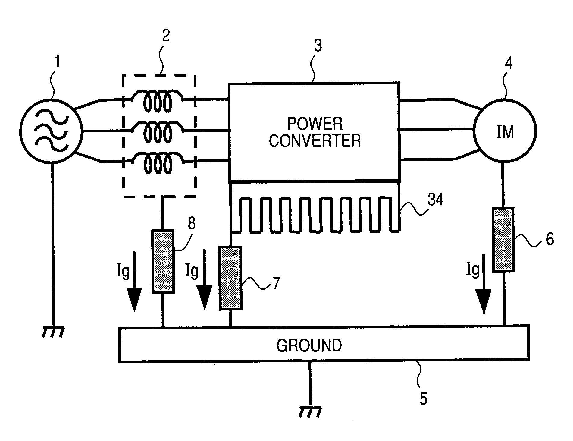
Therefore, a frequency of EMI (electromagnetic interference) noise generated from a system using a power converter is increased and is liable to invade other electronic apparatus, information communicating apparatus or the like as common mode noise via a stray capacitance and electromagnetic hazard is liable to generate.
However, a current at a frequency bond equal to or higher than several MHz constituting a noise current is diffused and propagated at a surface of the conductor by a skin effect and therefore, in the case of a high frequency current flowing in the direct current buses 300p, 300n by switching operation of the power converter, not only a conducting EMI noise but also a radiating EMI noise pose a problem.
Further, the elements constituting the power converter are constituted by three-dimensional structures and therefore, such a radiating noise is easily propagated via stray capacitances among the respective elements and a countermeasure thereagainst is becoming difficult.
A concentrated constant filter of a background art cannot control an EMI noise diffused on a surface of a power transmission line.

Method used


Image

  • Power converter and system using the same
  • Power converter and system using the same
  • Power converter and system using the same

Examples


Embodiment Construction

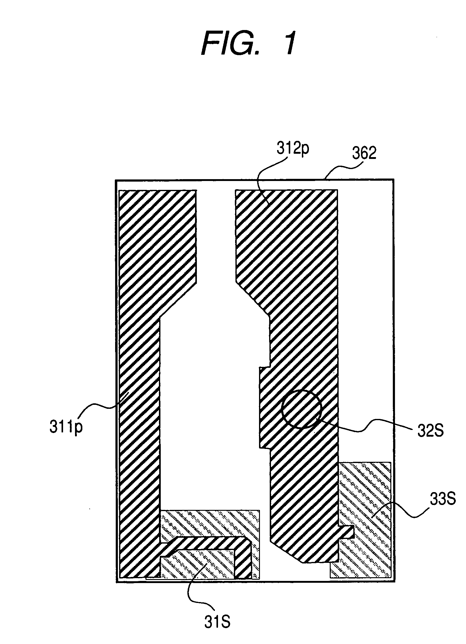
[0039] An explanation will be given of an embodiment of the invention in reference to the drawings as follows. FIG. 1 is a view showing an outline constitution of an essential portion of a power converter according to the embodiment of the invention, showing an outline constitution of the second wiring layer 362 of the multilayer wiring board constituting the power converter. The second wiring layer 362 is provided with the first positive side direct current wiring 311p and the second positive side direct current wiring 312p constituting the direct current bus 300p. One end of the first positive side direct current wiring 311p is outputted to the output terminal of the converter 31 (not illustrated in FIG. 1) arranged at the converter arranging region 31S, and one end of the second positive side direct current wiring 312p is outputted to the input terminal of the inverter 33 (not illustrated in FIG. 1) arranged at the inverter arranging region 33S. Other ends of the first positive s...


PUM


Abstract

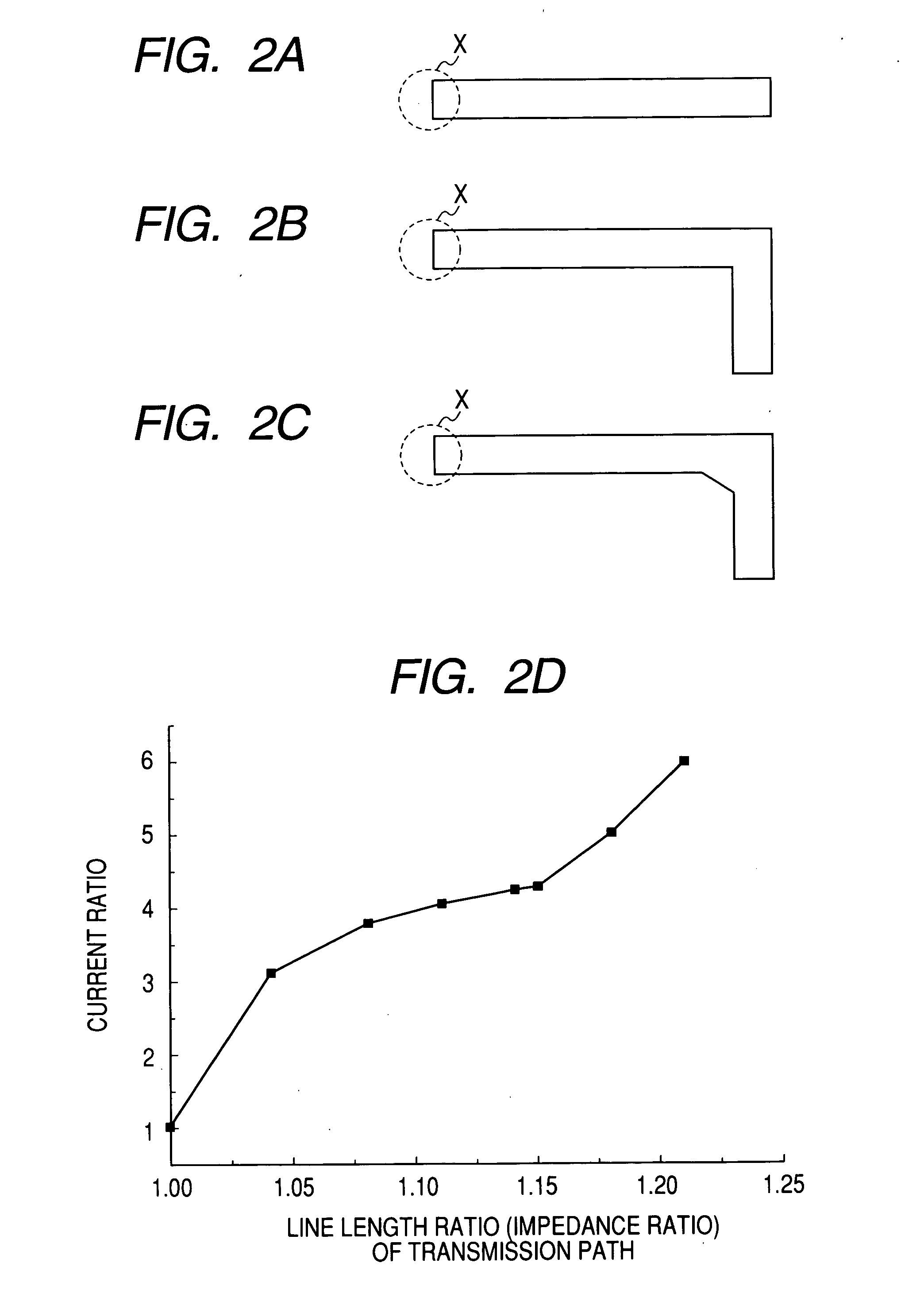
A second wiring layer 362 of a multilayer wiring board constituting a power converter is provided with a first positive side direct current wiring 311p and a second positive side direct current wiring 312p constituting a direct current bus 300p. The first positive side direct current wiring 311p and the second positive side direct current wiring 312p as well as a negative side direct current wiring are provided with a bent structure for making a transmission path length on one side in a direct current transmitting direction shorter than a transmission path length on other side thereof. Line widths of the first positive side direct current wiring 311p and the second positive side direct current wiring 312p are set to a width equal to or larger than a width by which a damping factor of a noise current in the direct current transmitting direction becomes substantially a constant value.

Description

BACKGROUND OF THE INVENTION [0001] The present invention relates to a power converter for carrying out a control by switching operation and a system using the same. [0002] A power converter controlled by switching operation is used in various apparatus of motor driving apparatus or the like and a function requested thereto becomes severe. In order to meet the needs, a switching characteristic of a power element constituting a power converter is improved and a switching period is considerably accelerated to 10 ns through 100 ns. Therefore, a frequency of EMI (electromagnetic interference) noise generated from a system using a power converter is increased and is liable to invade other electronic apparatus, information communicating apparatus or the like as common mode noise via a stray capacitance and electromagnetic hazard is liable to generate. [0003] A common mode current (leakage current) flowing in a motor driving system is made to flow via a stray capacitance distributed in the ...

Claims


Application Information

Patent Timeline
Patent Type & Authority Applications(United States)
IPC IPC(8): H02M7/12H02M5/458H02M7/00H02M7/48H05K1/02
CPCH02M1/44H02M5/458H02M7/003H05K1/0216H05K1/0231
Inventor MUTOH, NOBUYOSHI
Owner KEIO UNIV
Learn More