
High efficiency power converter with synchronous rectification

Inactive Publication Date: 2005-08-11
DELTA ELECTRONICS INC
View PDF9 Cites 37 Cited by
  • Summary
  • Abstract
  • Description
  • Claims
  • Application Information

AI Technical Summary

Benefits of technology

[0007] It is a first aspect of the present invention to provide a novel high efficiency AC-to-DC power converter with synchronous rectification. The power converter includes a rectifier for generating a rectified voltage from an ac power source, a boost converter electrically connected to the rectifier for converting the rectified voltage to a regulated bus voltage, a DC-to-DC converter electrically connected to the boost converter for converting the regulated bus voltage to an output voltage, and a controller generating a signal in response to the regulated bus voltage to provide a feedback control over the boost converter, so that the regulated bus voltage is further controlled and regulated.
[0016] It is a second aspect of the present invention to provide a novel high efficiency AC-to-DC power converter with synchronous rectification. The power converter includes a dual boost converter having a first boost circuits and a second boost circuits respectively and electrically connected to an output terminal and a return terminal of an ac power source for converting an AC input voltage to a regulated bus voltage, a DC-to-DC converter electrically connected to the dual boost converter for converting the regulated bus voltage to an output voltage, and a controller generating a signal in response to the regulated bus voltage to provide a feedback control over the dual boost converter, so that the regulated bus voltage is further controlled and regulated.
[0024] It is a third aspect of the present invention to provide a method for supplying a dc voltage from an ac power source which reduces the maximum power loss and solves the thermal issue when the power density of the power converter being increased. The method includes steps of rectifying an ac input voltage from the ac power source to produce a rectified voltage, converting the rectified voltage to a regulated bus voltage by means of a boost converter, detecting the regulated bus voltage by means of a controller and generating a signal in response to the regulated bus voltage to provide a feedback control over the boost converter, and converting the regulated bus voltage to an output voltage by means of a DC-to-DC converter.

Problems solved by technology

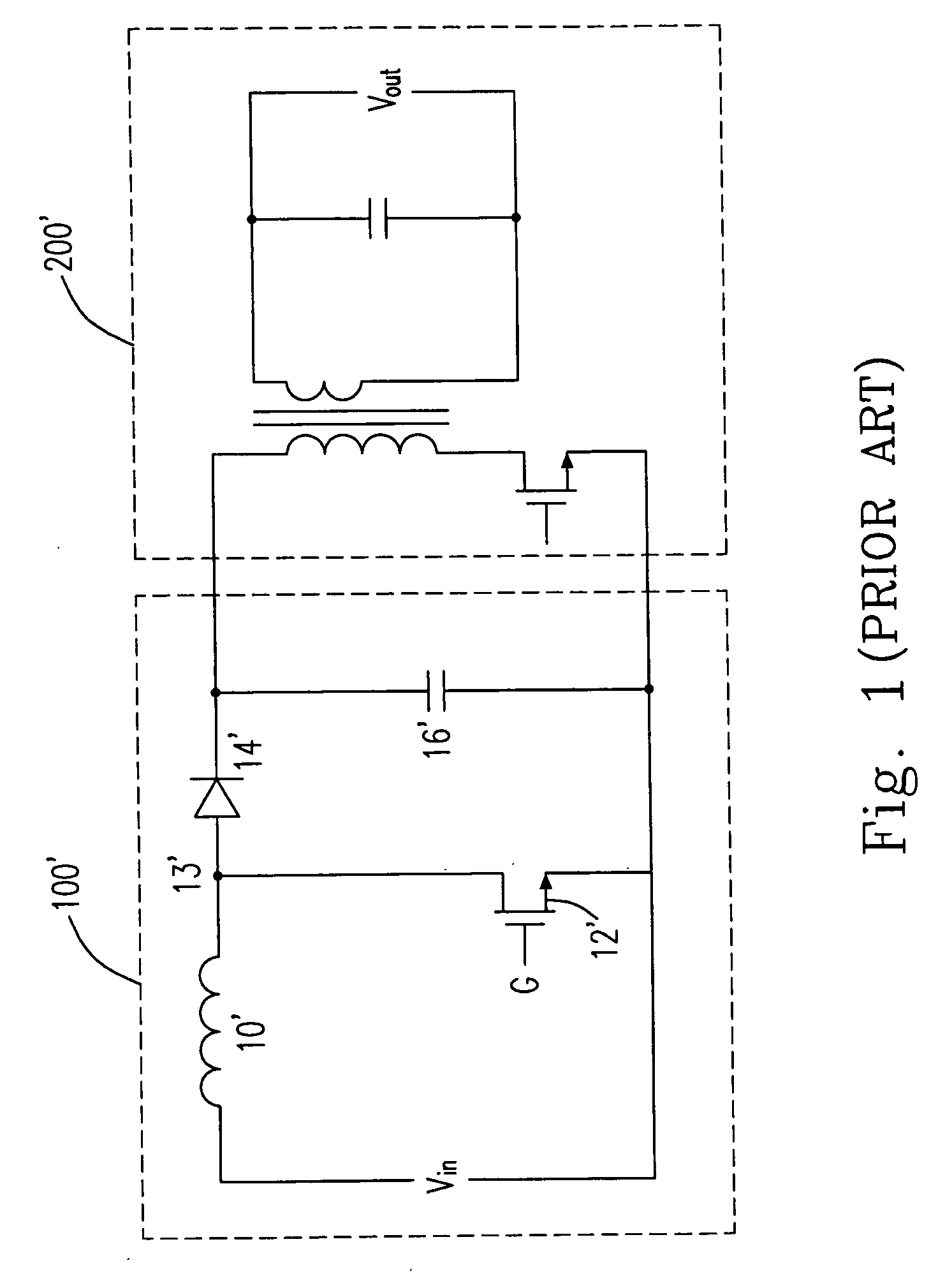
However, such an arrangement of the boost type PFC pre-regulator 100′ and DC-to-DC converter 200′ still has some problems in controlling and minimizing the overall power losses of the AC-to-DC power converter.
Considering the necessity for universal ac voltage input operation of the AC-to-DC power converter, the efficiency of the boost type PFC pre-regulator 100′ will drop dramatically at low input ac voltage due to the large period of on-time of the switch 12′ and results in higher conduction loss in the device.
However, most of the DC-to-DC power converters features in conversion efficiency as lower at higher input voltage but higher at lower input voltage operation, which means that the AC-to-DC power converter will actually show low overall conversion efficiency by said arrangement, and obviously the performance will be the worst in the minimum ac voltage input operation.

Method used


Image

  • High efficiency power converter with synchronous rectification
  • High efficiency power converter with synchronous rectification
  • High efficiency power converter with synchronous rectification

Examples


Embodiment Construction

[0032] The present invention will now be described more specifically with reference to the following embodiments. It is to be noted that the following descriptions of preferred embodiments of this invention are presented herein for purpose of illustration and description only; it is not intended to be exhaustive or to be limited to the precise form disclosed.

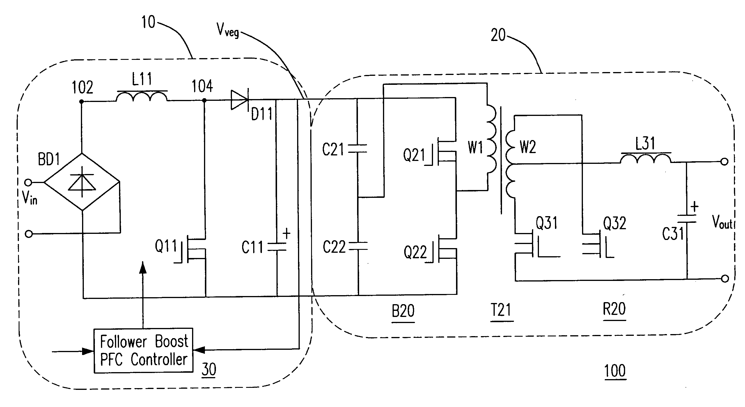
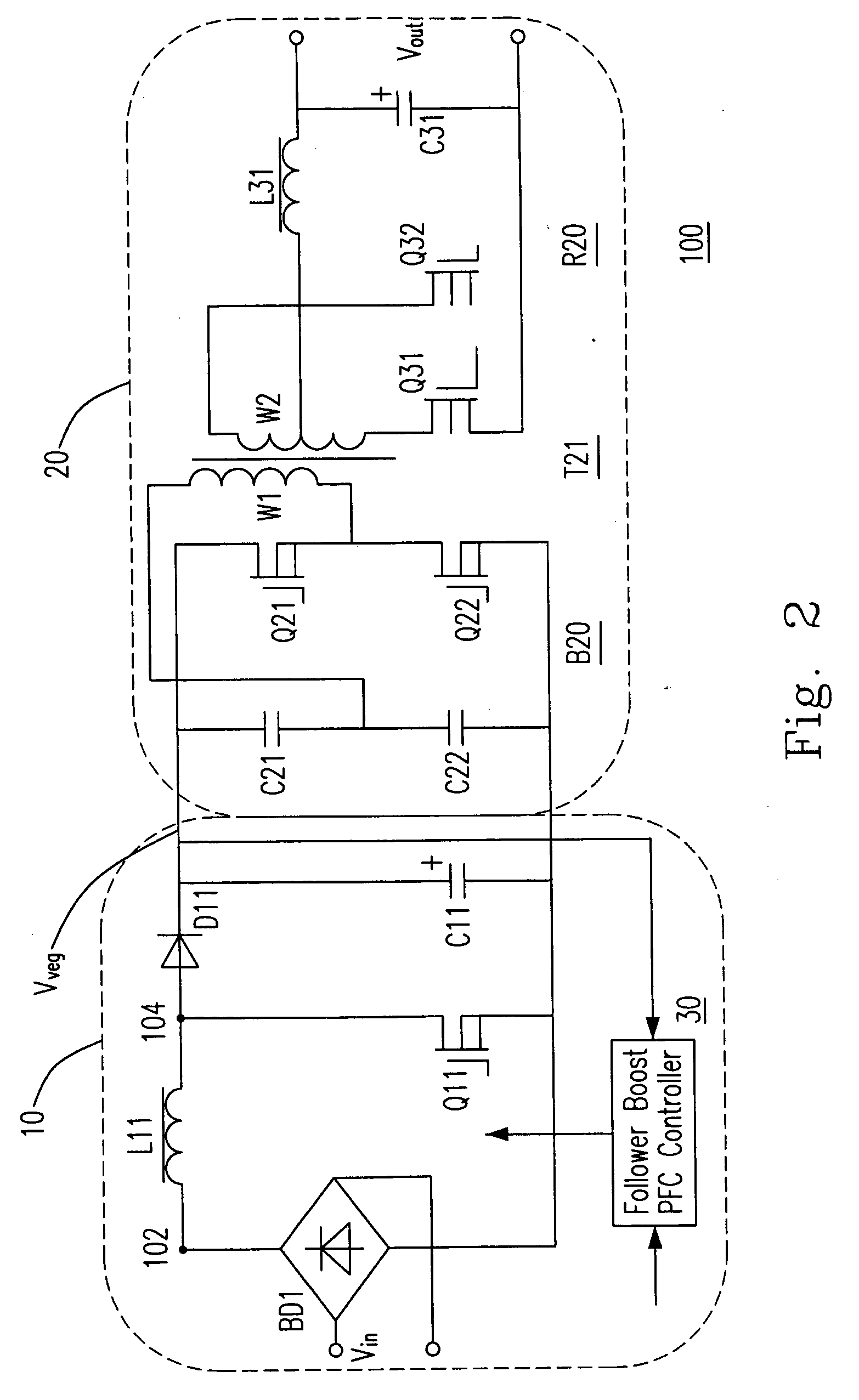
[0033] Please refer to FIG. 2, which shows a schematic diagram of a power converter according to the first preferred embodiment of the present invention. The power converter is composed by a boost type PFC pre-regulator 10 and a DC-to-DC converter 20. The boost type PFC pre-regulator 10 is employed to rectify an ac input voltage Vin, then draw a sinusoidal input current from the ac input voltage Vin to meet the limits of harmonic current emission, and output a regulated bus voltage of which the amplitude varies with that of ac input voltage. The DC-to-DC converter 20 is used for converting the regulated bus voltage to an tight ...


PUM


Abstract

This invention provides an AC-to-DC power converter that improves the overall conversion efficiency especially that at the minimum input ac voltage for universal input operation design by adopting a new combination of control strategies and topologies for the PFC pre-regulator and DC-to-DC converter. The PFC pre-regulator was arranged to provide a regulated bus voltage of which the amplitude is varied in accordance with input ac voltage by a follower boost controller to achieve best efficiency in minimum input ac voltage operation. A synchronous rectifier dual boost PFC pre-regulator was present for further reduction of the power loss in the converter. Symmetrical half-bridge or symmetrical full bridge switch devices were arranged for the primary side of DC-to-DC converter and synchronous rectification circuit with two synchronous rectifier were arranged for the secondary side of the DC-to-DC converter as combination of the AC-to-DC converter. The two synchronous rectifiers were controlled to turn on and turn off complementary to that to the primary half-bridge switch devices to insure a minimized power loss of that converter stage for the extended bus voltage operation design.

Description

FIELD OF THE INVENTION [0001] The present invention relates to an AC-to-DC power converter, and more specifically to an AC-to-DC power converter with synchronous rectification. BACKGROUND OF THE INVENTION [0002] Many electronics appliances, such as computers and consuming electronics, are designed to operate with a direct current (dc) power. Therefore, AC-to-DC power converters are widely used to convert an alternating current (ac) power source into tight regulated dc voltage to supply the appliances. [0003] Please refer to FIG. 1, which shows a typical configuration of an AC-to-DC power converter. An AC-to-DC power converter generally includes two main parts, wherein the first part is a boost type PFC pre-regulator 100′ for providing a regulated bus voltage from a rectified input ac voltage Vin, and the second part is a DC-to-DC converter 200′ for providing a tight regulated voltage Vout from the bus voltage. [0004] The boost type PFC pre-regulator 100′ essentially includes a recti...

Claims


Application Information

Patent Timeline
IPC IPC(8): H02M3/335
CPCH02M3/33592Y02B70/1475H02M2001/007H02M1/007Y02B70/10
Inventor DOU, SENLIN, DONGXU, DAO FEIDUAN, JUNZHANG, ALPHA J.
Owner DELTA ELECTRONICS INC
Learn More