
LED light

a technology of led light and led light, which is applied in the direction of light and heating apparatus, semiconductor devices of light sources, transportation and packaging, etc., can solve the problems of large amount of energy wasted, low economic efficiency, and inability to convert electrical energy into light energy, so as to maximize the life of the lamp. , the effect of high illumination intensity

Inactive Publication Date: 2005-08-11
DAEJIN DMP
View PDF9 Cites 652 Cited by
  • Summary
  • Abstract
  • Description
  • Claims
  • Application Information

AI Technical Summary

Benefits of technology

[0010] Therefore, the present invention has been made in view of the above problems occurring in the prior art, and it is an object of the present invention to provide an LED light using LED, in which a variety of applications can be achieved by providing a structure capable of being inserted into a receptacle and thus substituting for the electric bulbs and the halogen lamps, a high intensity of illumination can be achieved with a small amount of energy, an adequate intensity of illumination conforming to the user's desire can be obtained by modularizing LED and providing an appropriate spatial arrangement, and the lifespan thereof can be maximized by providing an efficient cooling structure, while giving an adequate performance when continuously used.

Problems solved by technology

However, there is a limitation in converting the electrical energy into a light energy, and thus a large amount of energy has been wasted.
The economical efficiency thereof still remains low due to its manufacturing cost.
However, after used for a certain period of time, the LED is deteriorated in the efficiency thereof.
Also, when it is continuously operated, the amount of heat generated is gradually increased, thereby reducing the lifespan thereof.
However, similarly, it embraces a problem in that the lifespan is reduced, due to the heat generation.

Method used


Image

  • LED light
  • LED light
  • LED light

Examples


Embodiment Construction

[0027] The preferred embodiments of the invention will be hereafter described in detail, with reference to the accompanying drawings.

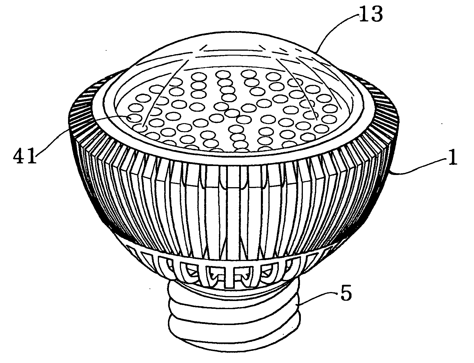
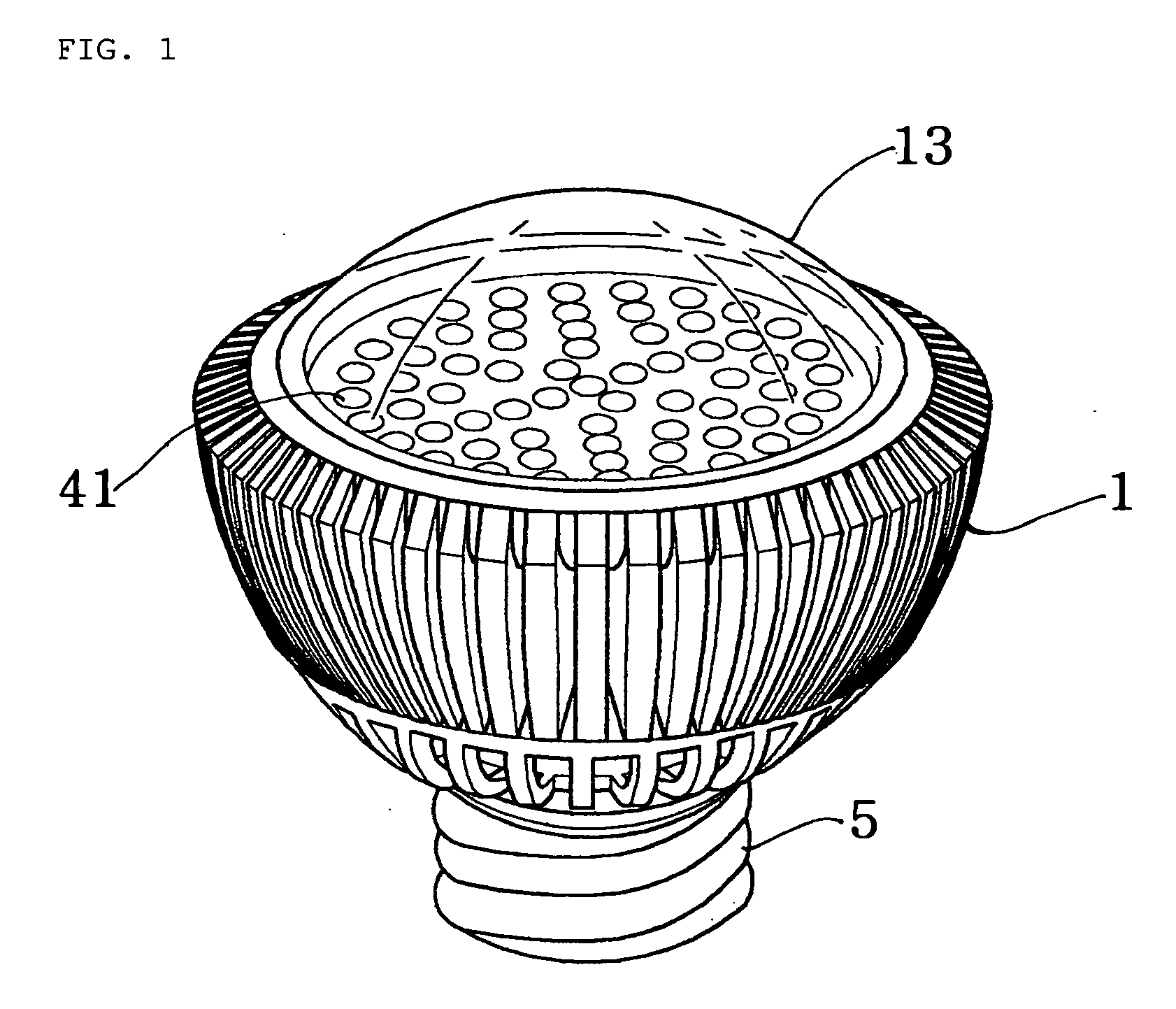
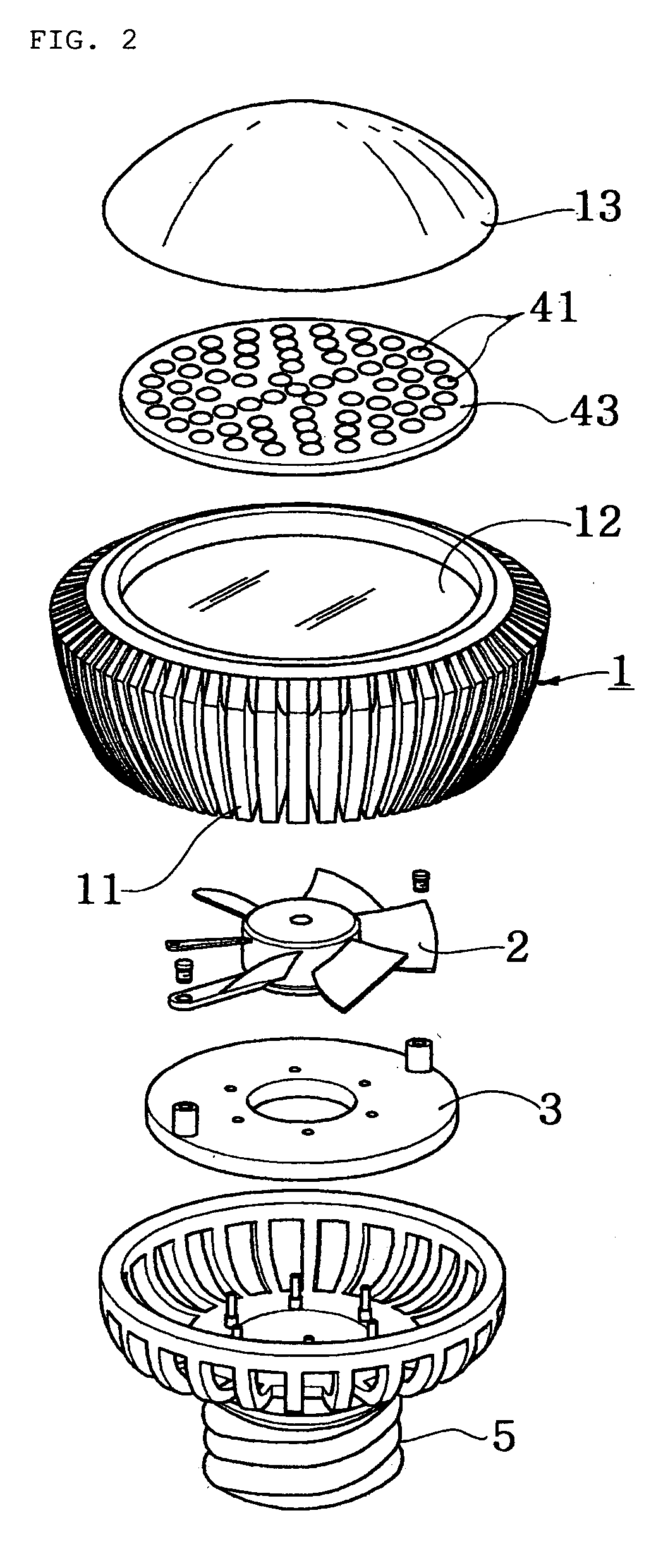
[0028]FIG. 1 is a perspective view of an LED light according to one embodiment of the invention, and FIG. 2 is an exploded view of the LED light of FIG. 1.

[0029] As illustrated in FIGS. 1 and 2, there is shown the LED light of the invention including a socket 5 electrically connected to a receptacle, a cooling fan 2 for forcibly circulating air, and a main body 1 for receiving the cooling fan 2 and having a plurality of radial partition walls 11 for ventilation. A plurality of LEDs 41 is attached to the periphery and / or the leading edge of the main body 1. A circuit board 3 is provided in order to control in such a way that an alternating current supplied from the socket 5 is rectified into a direct current, which is supplied to the cooling fan 2 and the LED 41.

[0030] Referring to FIGS. 1 and 2, the socket 5 has a male thread formed thereon or a con...


PUM


Abstract

Disclosed herein is an LED light. The LED light comprises a socket electrically connected to a receptacle, and a cooling fan for forcibly circulating air. The cooling fan is received in a main body, which has a plurality of radial partition walls formed on the outer peripheral surface thereof in such a manner as to be spaced apart from one another with a gap having a slit shape for ventilation. A plurality of LEDs is attached to the outer periphery and / or the inner leading edge of the main body. A circuit board is provided to control the light such that an alternating current supplied from the socket is rectified into a direct current, which is supplied to the cooling fan and the LED.

Description

BACKGROUND OF THE INVENTION [0001] 1. Field of the Invention [0002] The present invention relates to an LED light using LED, in which the illumination thereof can be significantly improved and the lifespan thereof can be innovatively extended, while functioning as an illumination lighting such an electric bulb or a lamp. [0003] 2. Background of the Related Art [0004] An illumination light is a device, which is supplied with an electric power and transforms the electrical energy into a light energy. The light energy is used for illuminating an object and discerning it in a dark place. This illuminating tool has made a great contribution to epochal advancement in human civilization. The illumination light is utilized in various forms. The initial incandescent bulb has been developed into a fluorescent lamp, and then various electric lights have been developed, including a searchlight containing nitrogen or helium gas therein or a halide lamp or a natrium lamp. [0005] However, there is...

Claims


Application Information

Patent Timeline
IPC IPC(8): F21K99/00F21V29/02
CPCF21K9/135F21V3/02F21V23/02F21Y2101/02F21Y2111/004F21V29/89F21V29/507F21V29/677F21V29/773F21V29/83F21V29/506F21K9/232F21Y2115/10F21Y2107/20F21K9/235F21K9/237F21V19/0025F21Y2107/30
Inventor PARK, CHANG SIK
Owner DAEJIN DMP
Learn More