
Disposable mask system

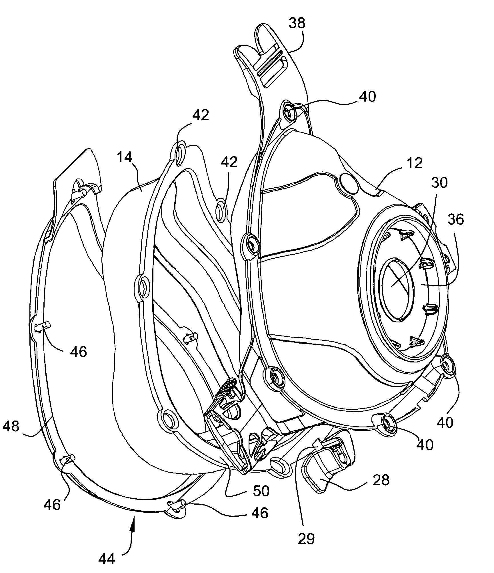
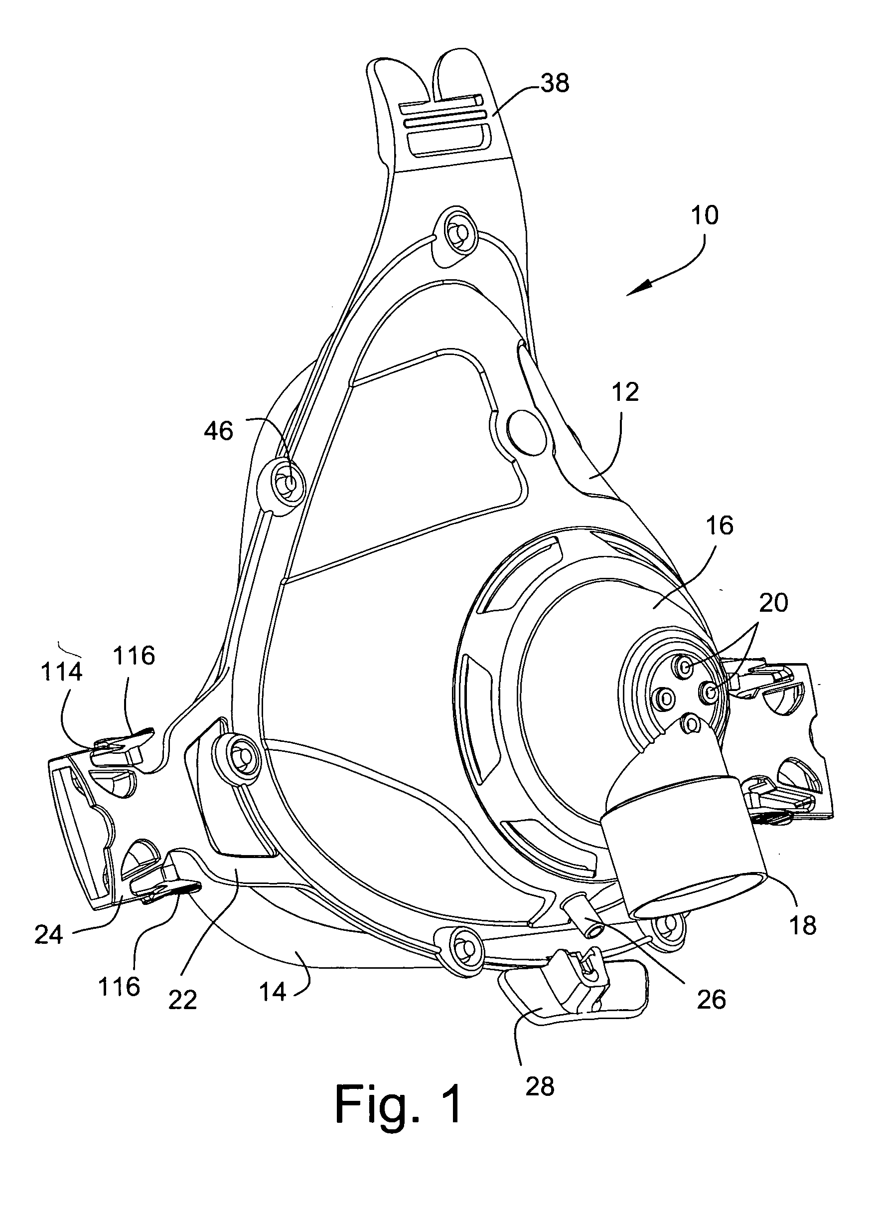
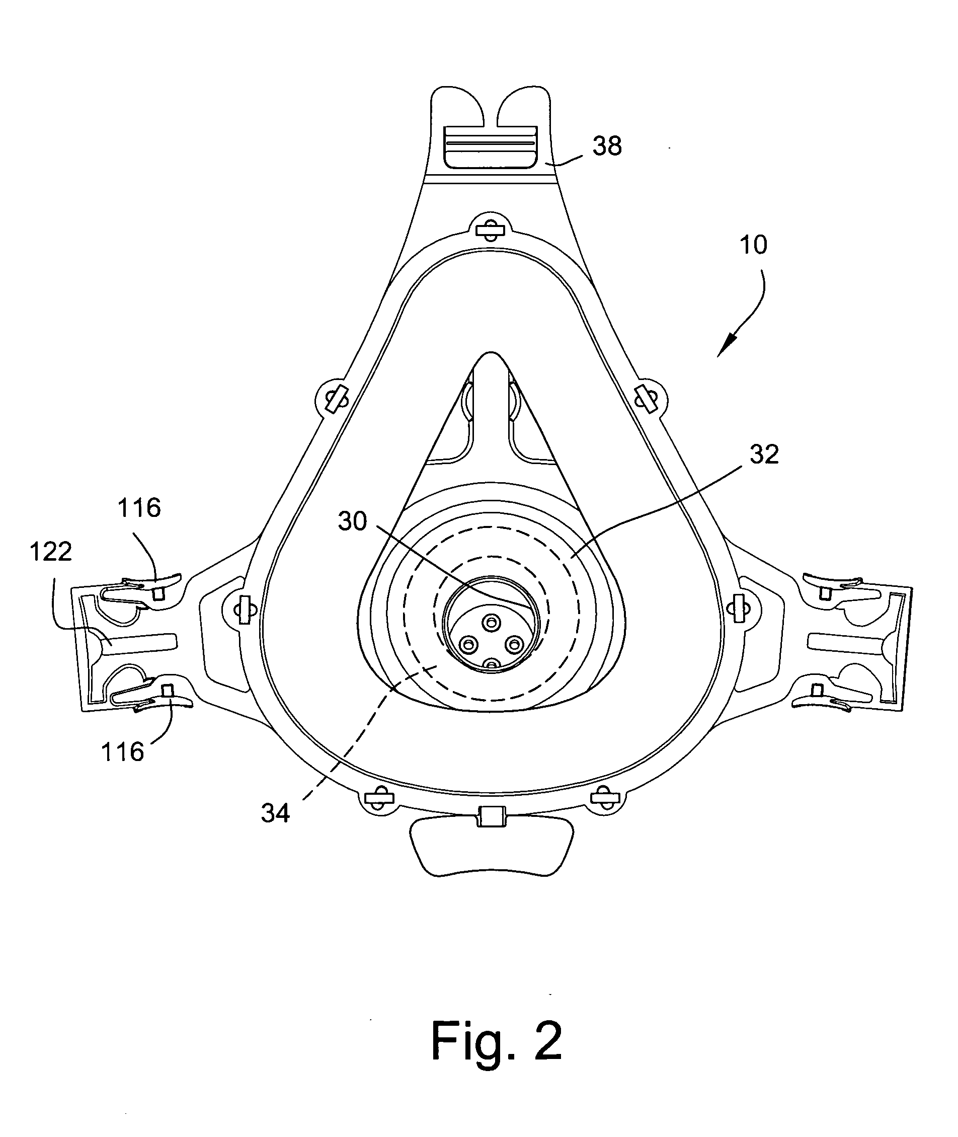
a mask system and mask technology, applied in the field of mask systems, can solve the problems of not being displayed, masks can be accidentally re-used in a manner, masks do not provide fully adequate and/or optimal solutions, etc., and achieve the effect of low cost and high differentiation

Active Publication Date: 2005-08-11
LEXMARK INT INC +1
View PDF53 Cites 150 Cited by
  • Summary
  • Abstract
  • Description
  • Claims
  • Application Information

AI Technical Summary

Benefits of technology

[0009] Another aspect of the invention is to provide a disposable mask which has a useful life of either a single use or can be used over a short period of time, e.g., 7-10 days or more. Preferably, the mask can be used only up to 7 days.
[0011] Yet another aspect of the invention is to provide a mask assembly which is difficult to disassemble without breaking, thereby discouraging multiple use and preventing removal of safety components such as an anti-asphyxia valve.
[0014] Another aspect of the invention is to provide a low cost mask with high differentiation between disposable and reusable products, in terms of functionality, aesthetics and / or durability.

Problems solved by technology

While this mask performs strongly for seal and comfort, it may not display characteristics that are most amenable for hospital and clinical use, which can differ from the characteristics most suitable for home or other uses.
These related art masks do not provide fully adequate and / or optimum solutions for use of mask systems in a hospital or clinical environment.
Therefore, these masks can be accidentally re-used in a manner that could be dangerous to the patient, e.g., the risk of spread of germs, etc.

Method used


Image

  • Disposable mask system
  • Disposable mask system
  • Disposable mask system

Examples


first embodiment

[0097]FIG. 35 illustrates headgear 124 according to the present invention. Headgear 124 may be manufactured by starting with a substantially flat piece of appropriate material, such as polyester loop material, Breathoprene®, leather, cloth, plastic, etc., and then cutting, scoring or weakening the headgear along predetermined cut lines 126 whereby the headgear 124 may be repositioned to approximate the shape of the patient's head. The headgear 124 may include side straps 128 and front strap 130. Side straps 28 may be created with a single slit 126. Also, in this example, main body 127 of strap has an appropriate amount of slits, e.g., 2-5 slits or more, to optimize coverage and stability of the headgear 124 or patient's head. Generally speaking, each of slits 126 expand in use to form a plurality of open spaces 126′, when the headgear is placed on the patient's head.

[0098] The positioning of the headgear 124, including the side straps 128 and front strap 130, in relation to the mask...

second embodiment

[0099]FIG. 38 illustrates headgear 134 according to the present invention. Headgear 134 includes side straps 136 and front strap 138. Again, the headgear 134 may be manufactured by providing a flat piece of material appropriate for use as headgear on a patient. Each side strap 136 is created by cutting the material along a predetermined cut line 140. The headgear 134 may include a plurality of additional cut lines 142, which creates a net-like configuration on the patient's head, as shown in FIGS. 39 and 40. Each cut line 142 forms an open area 142′, to effectively cup the patient's head. Open areas 142′ provide for ventilation of the patient's head. Open areas 142′ may be in the shape of a polygon, e.g., a triangle or a diamond. Of course, other headgear arrangement may also be used to support mask assembly on the patient's head.

[0100]FIG. 41 illustrates headgear 400 according to another embodiment of the present invention. Headgear includes side straps 402, 404 and a top strap 406...


PUM


Abstract

A mask system includes a frame, cushion, cushion clip, swivel elbow, headgear and / or headgear clips that are configured for use in a clinical or hospital environment. One or more components of the mask system are configured to promote single patient use, e.g., by providing an age indicator and / or preventing disassembly and / or cleaning, etc.

Description

CROSS-REFERENCE TO APPLICATIONS [0001] This application claims the benefit of U.S. Provisional Application Nos. 60 / 533,229, filed Dec. 31, 2003, 60 / 571,488, filed May 17, 2004, 60 / 588,341, filed Jul. 16, 2004, and 60 / 619,022, filed Oct. 18, 2004, each incorporated herein by reference in its entirety.BACKGROUND OF THE INVENTION [0002] 1. Field of the Invention [0003] The present invention relates to a disposable mask system for use with patients, e.g., adult patients, for the treatment of obstructive sleep apnea (OSA) or the provision of non-invasive positive pressure ventilation (NIPPV) support using continuous positive airway pressure (CPAP), bi-level, or other pressure support ventilators. The mask is intended for single patient, short-term use having a life span, e.g., of about 7-14 days. Preferably, the mask is only usable for up to 7 days. [0004] 2. Description of Related Art [0005] ResMed's Mirage® Disposable Full Face mask is formed of a frame with a double wall silicone cush...

Claims


Application Information

Patent Timeline
IPC IPC(8): A61M16/06A61M16/20A62B7/00A62B9/02A62B18/08
CPCA61M16/06A61M16/0683A61M16/0816A61M16/208A61M16/0633A61M2205/44A61M2205/581A61M2205/582A61M2205/583A61M2205/43A61M16/0825A61M16/0858A61M2205/0227
Inventor GING, ANTHONY MICHAELWORBOYS, DAVID JOHNSMART, GREGORY SCOTTDANTANARAYANA, MUDITHASNOW, JOHN MICHAELSTALLARD, PHILIP THOMAS
Owner LEXMARK INT INC
Learn More