Eureka AIR delivers breakthrough ideas for toughest innovation challenges, trusted by R&D personnel around the world.

Hernia mesh tacks

a mesh and hernia mesh technology, applied in the field of surgical tacks, can solve the problems of inconvenient removal of many of the tacks, injuring the tissue, damage to the hernia mesh, etc., and achieve the effect of facilitating insertion in tough tissue and increasing the drive surface area

Inactive Publication Date: 2005-08-04
TYCO HEALTHCARE GRP LP
View PDF59 Cites 110 Cited by
  • Summary
  • Abstract
  • Description
  • Claims
  • Application Information

AI Technical Summary

Benefits of technology

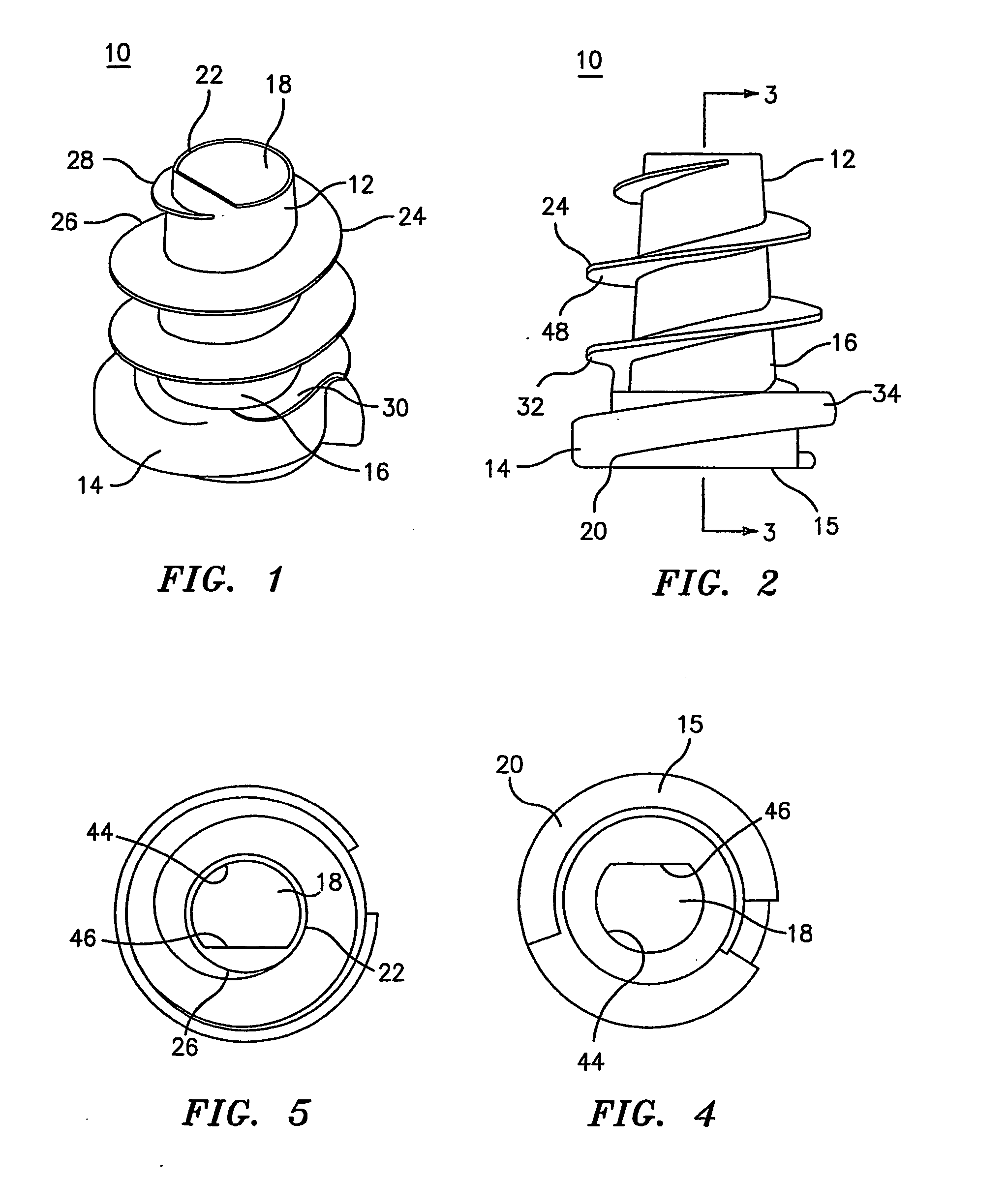
[0008] There are disclosed absorbable hernia tacks suitable for use in securing hernia mesh against tissue. The tacks generally include a barrel portion having a head extending distally therefrom. The barrel portion and the head define a throughbore for receipt of a drive rod of an insertion instrument so that the hernia tack can be driven through mesh and into tissue. The throughbore may have various non-circular shapes, such as D-shaped, rectangular, polygonal, etc., to increase the drive surface area and facilitate insertion in tough tissue. A tissue thread is formed on the barrel portion and is configured to engage tissue as the tack is rotated into the tissue. The tissue thread includes a leading edge at the distal end of the barrel portion and a trailing edge at a proximal end of the barrel portion. The leading edge has the advantage of following a tip of an insertion tool to allow a traumatic entry of the tack into tissue.
[0010] In various embodiments of the surgical tacks, the proximal and distal surfaces of the tissue thread may form various acute or obtuse angles relative to the barrel portion. These angles provide the advantages of increasing the hold of the thread in tissue and allowing for easier insertion and / or removal of the tack from tissue. Alternatively, one or more of these surfaces may be perpendicular to the barrel portion. It should be noted that the drive thread has a substantially greater diameter than the tissue thread to allow the head to seat against the mesh without entering the hold in the mesh formed by the barrel and tissue thread. The drive thread and the tissue thread are not connected that is, i.e., are discontinuous with respect to each other to achieve this advantage.
[0011] There is also disclosed an insertion tool for inserting one or more hernia tacks through mesh and into tissue. The insertion tool generally includes an elongated outer tube which is affixed at its distal end to a handle mechanism. The insertion tool also includes an inner drive rod which is rotatably connected to the handle mechanism. A pointed tip of the drive rod forms an atraumatic transition with the atraumatic tip of the barrel portion to prevent tearing mesh and tissue as the tack is inserted therethrough. Various known handle mechanisms may be utilized to rotate the inner drive rod with respect to the stationary outer tube. An inner thread may be provided within the outer tube so as to engage the drive thread of the head of the hernia tack. Preferably, the distal end of the inner thread is flush with the distal end of the outer tube so that in the event a tack need be removed, the insertion tool may be positioned over the drive cap of the tack and rotated in an opposite direction to draw the tack back into the insertion tool and thereby remove the tack from the body.

Problems solved by technology

One method of affixing mesh to tissue is through the use of surgical screws or tacks; However, known tacks may have a traumatic distal end which causes damage to the hernia mesh and unnecessarily injures the tissue as the tack is being inserted.
Furthermore, many of these tacks are not configured to be removed after they have been implanted in the patient.

Method used


Image

  • Hernia mesh tacks
  • Hernia mesh tacks
  • Hernia mesh tacks

Examples


Embodiment Construction

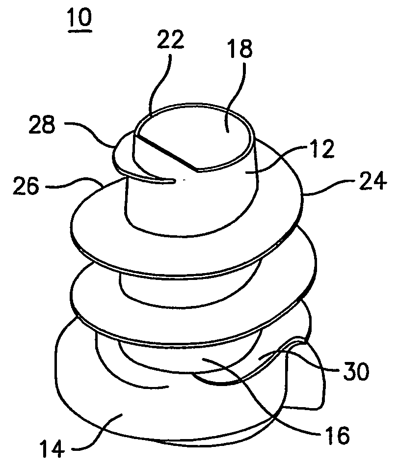
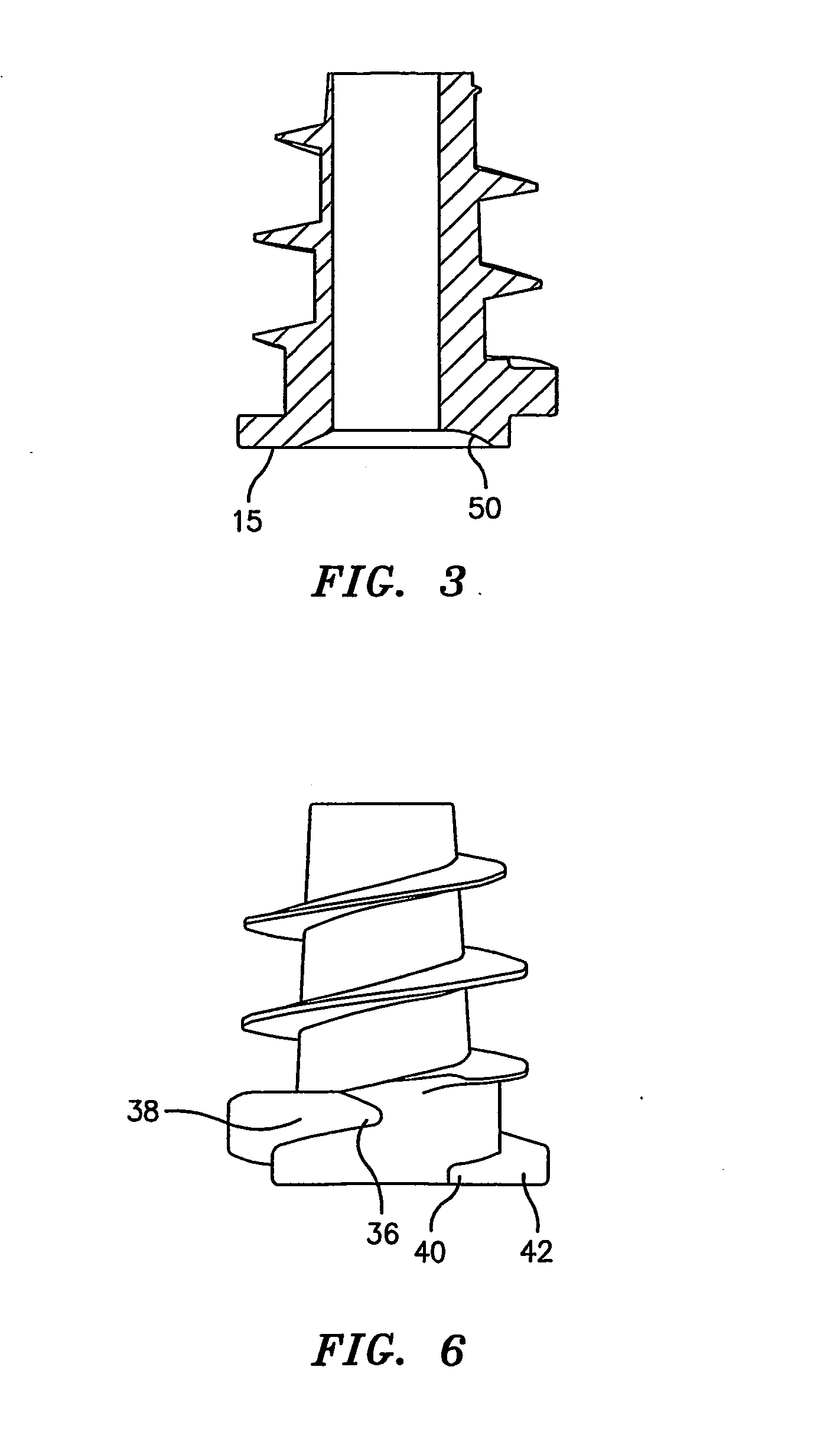
[0039] Referring to FIGS. 1 and 2, there is disclosed a hernia tack suitable for atraumatic insertion through hernia mesh and into human tissue. Hernia tack 10 generally includes an elongated barrel portion 12 having a cap or head 14 at a proximal end 16 of barrel portion 12. Barrel portion 12 extends distally from head 14 and is preferably tapered. A detent may be formed in a proximal surface 15 of head 14 for receipt of driving instrumentation. Preferably barrel portion 12 and head cap 14 define a throughbore 18 therethrough. Throughbore 18 extends from a proximal end 20 of head cap 14 to a distal end 22 of barrel portion 12.

[0040] Preferably, distal end 22 is smooth or rounded off to avoid traumatizing tissue and damaging the mesh as tack 10 is installed. Distal end 22 forms an atraumatic transition with the tip of a drive rod to prevent tearing of mesh and tissue during insertion. Tack 10 can be formed of any biocompatible material and preferably of a material that is absorbabl...


PUM


Abstract

There are disclosed various embodiments of surgical tacks for use in surgical procedures. The tacks generally include a head and a barrel portion extending distally from the head. Preferably the head and the barrel portion define a throughbore for receipt of a drive instrument. A thread on the head is provided to engage threads in the installation tool. A tissue thread is provided on the barrel, portion to engage tissue. Distal and proximal surfaces of the tissue thread may be oriented at various angles relative to the barrel portion. There is also disclosed an insertion instrument to insert one or more tacks as well as a method of use. There is further disclosed a model device for use in explaining the operation of the instrument.

Description

[0001] This application claims priority from provisional application Ser. No. 60 / 388,119 filed Jun. 11, 2002, all of which is incorporated herein in its entirety by reference.BACKGROUND [0002] 1. Technical Field [0003] The technical field relates to surgical tacks for use in securing mesh during a hernia repair procedure and, more particularly, to absorbable surgical tacks and insertion instruments. [0004] 2. Background of Related Art [0005] During hernia repair surgery it is often necessary to affix a section of mesh over the herniated tissue. This is often accomplished through the use of staples or sutures or other affixation type means. [0006] One method of affixing mesh to tissue is through the use of surgical screws or tacks; However, known tacks may have a traumatic distal end which causes damage to the hernia mesh and unnecessarily injures the tissue as the tack is being inserted. Furthermore, many of these tacks are not configured to be removed after they have been implanted...

Claims


Application Information

Patent Timeline
Patent Type & Authority Applications(United States)
IPC IPC(8): A61B17/00A61B17/58A61B17/064A61B17/068A61B17/08A61B17/86A61B17/88A61F2/00
CPCA61B17/00234A61B17/064A61B17/068A61B17/861A61B17/8615A61B17/8625A61B17/72A61B2017/00004A61B2017/0648A61F2/0063A61B17/08A61B17/10A61F2220/0016A61B17/888A61F2002/0072A61B17/8888A61B17/863A61B17/864A61B17/8645A61B17/105
Inventor CRISCUOLO, CHRISTOPHER J.ARANYI, ERNIE
Owner TYCO HEALTHCARE GRP LP
Why Eureka
Eureka Blog
Learn More