Portable computer and method for mounting a flat panel display device thereon
a flat panel display and computer technology, applied in the direction of identification means, electrical apparatus casings/cabinets/drawers, instruments, etc., can solve the problem of undesirable large display cases, and achieve the effect of reducing the non-display area of the lcd devi
- Summary
- Abstract
- Description
- Claims
- Application Information
AI Technical Summary
Benefits of technology
Problems solved by technology
Method used
Image

Examples
second embodiment
[0047]FIGS. 4A-4C show the present invention. Referring to FIGS. 4A and 4B, the LCD device 10 has an LCD panel 12, a backlight unit 14, and a supporting frame 16. FIG. 4C shows an example of a detailed structure of the LCD device shown in FIGS. 4A and 4B. Referring to FIG. 4C, the LCD device 10 has a first frame 14g, preferably made of plastic, a reflector 14f on the frame 14g, a light guide film 14e, a diffuser or protecting film 14d, a first prism sheet 14c, a second prism sheet 14b, another diffuser or protecting film 14a, and the LCD panel 12. The first frame 14g is coupled to a second frame or supporting frame 16. At each corner of the first frame 14g a screw hole is preferably formed. Although FIG. 4C shows the first frame 14g as part of the backlight unit 14, the first frame 14g can act as the supporting frame 16.
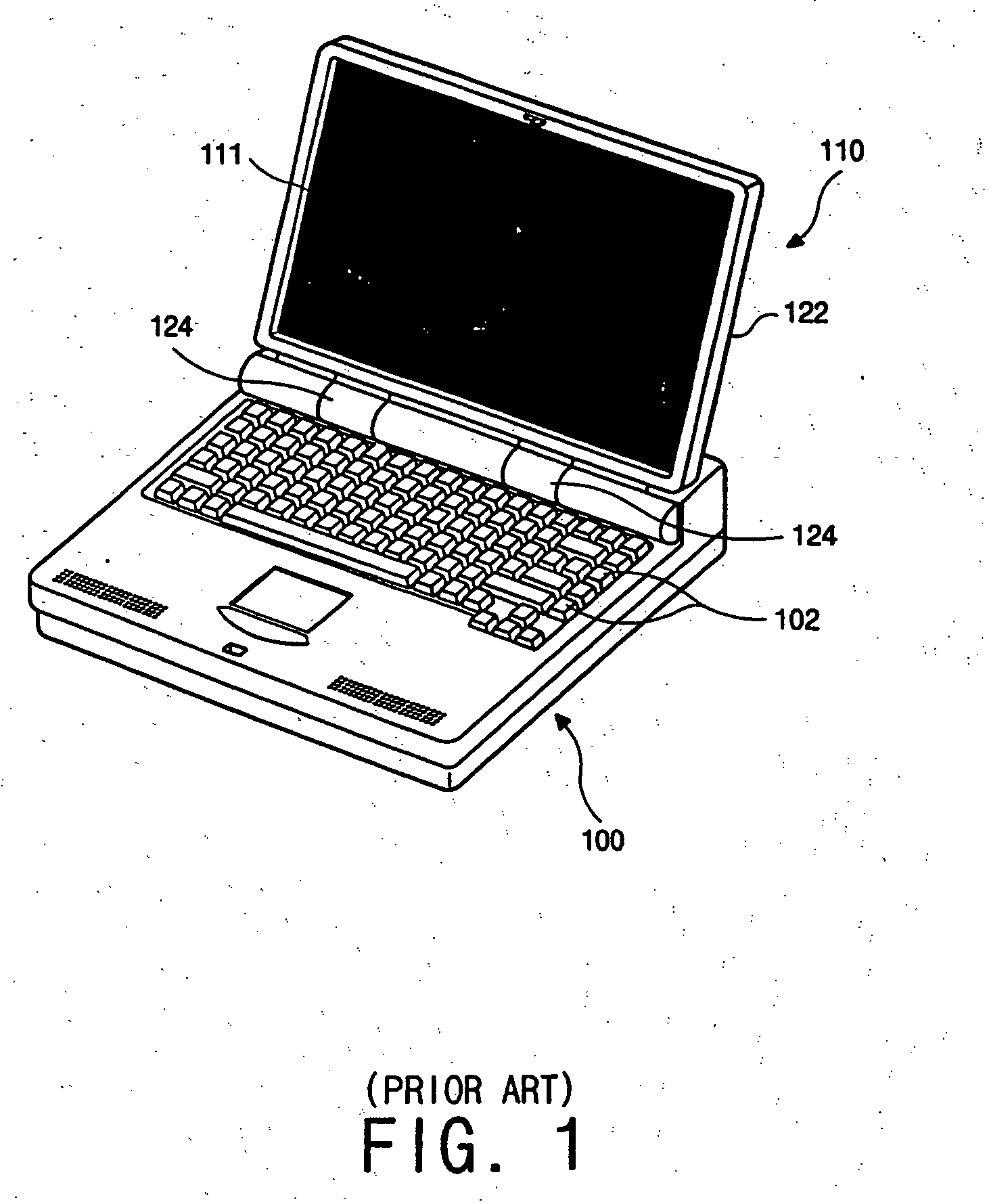
[0048] To mount the LCD device 10 to the display case 122 (FIG. 1), the LCD device 10 is placed on the inner surface of the display case 122. Then, the case 122 and ...
first embodiment
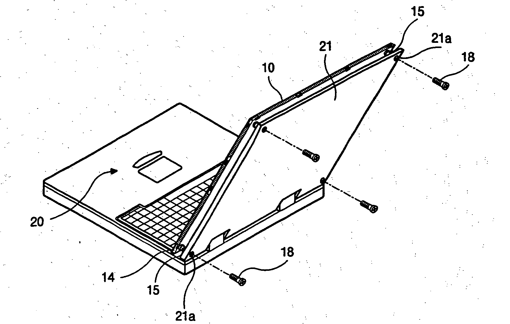
[0050]FIG. 5 shows the assembly of the LCD device 110 to the case 21 of a portable computer according to the present invention. The computer includes a body 20 having an information input device. The case 21 may cover the body 20 and is coupled to the body through a hinge mechanism. Preferably at each corner of the case 21 a through-hole 20a is formed.
[0051] To mount the LCD device 10 to the case 21, the LCD device 10 is placed on the inner surface of the case 21 such that the positions of the holes 20a and the holes 5 coincide with each other, and screws 18 are inserted into the holes 21a and 15 from the back of the case 21. The through-hole 21a is preferably stepped so that the head of the screw 18 will not protrude from the outer surface of the case 21.
[0052] Although not shown in FIG. 5, the front case such as shown in FIG. 2 is preferably assembled with the case 21 for covering the edges of the LCD device 10.
[0053]FIG. 6 shows a back mounting structure of the LCD device accor...
third embodiment
[0056]FIG. 8 is a perspective view showing a mounting structure of the LCD device according to the present invention. There may be one or more binge mechanisms for the LCD device; however, for convenience of explanation, only one hinge mechanism will be explained.
[0057] Referring to FIG. 8, a body 20 includes a hinge mount 22, where a hinge arm 24 is connected. The hinge arm 24 has a pin portion 24a and a flat or extended portion 24b. The former is for being mounted to the hinge mount 22, and the latter is for being coupled to the rear surface of the LCD device 10. The various hinge components may be separate pieces of attached members or a single structure.
[0058] The flat portion 24b can be elongated in various directions and by various methods. FIG. 8 shows one example of the flat portion 24b which is in the shape of an inverted “F.” At each end of the flat portion 24b, a hole such as a through-hole 24c is preferably formed. At the back surface of the LCD device 10, mounting hole...
PUM
| Property | Measurement | Unit |
|---|---|---|
| area | aaaaa | aaaaa |
| size | aaaaa | aaaaa |
| width d2 | aaaaa | aaaaa |
Abstract
Description
Claims
Application Information
 - R&D
- Intellectual Property
- Life Sciences
- Materials
- Tech Scout
- Unparalleled Data Quality
- Higher Quality Content
- 60% Fewer Hallucinations
Browse by: Latest US Patents, China's latest patents, Technical Efficacy Thesaurus, Application Domain, Technology Topic, Popular Technical Reports.
© 2025 PatSnap. All rights reserved.Legal|Privacy policy|Modern Slavery Act Transparency Statement|Sitemap|About US| Contact US: help@patsnap.com