
Closed loop additive injection and monitoring system for oilfield operations

a monitoring system and closed-loop technology, applied in the field of oilfield operations, can solve the problems of reducing hydrocarbon production, requiring expensive rework operations or even abandoning the wellbore, and reducing the life of the wellbore itsel

Inactive Publication Date: 2005-08-04
BAKER HUGHES INC
View PDF55 Cites 91 Cited by
  • Summary
  • Abstract
  • Description
  • Claims
  • Application Information

AI Technical Summary

Problems solved by technology

Insufficient amounts of treatment additives can increase the formation of corrosion, scale, paraffins, emulsion, hydrates etc., thereby reducing hydrocarbon production, the operating life of the wellbore equipment and the life of the wellbore itself, requiring expensive rework operations or even the abandonment of the wellbore.
Excessive corrosion in a pipeline, especially a subsea pipeline, can rupture the pipeline, contaminating the environment.
Repairing subsea pipelines can be cost-prohibitive.

Method used


Image

  • Closed loop additive injection and monitoring system for oilfield operations
  • Closed loop additive injection and monitoring system for oilfield operations
  • Closed loop additive injection and monitoring system for oilfield operations

Examples


Embodiment Construction

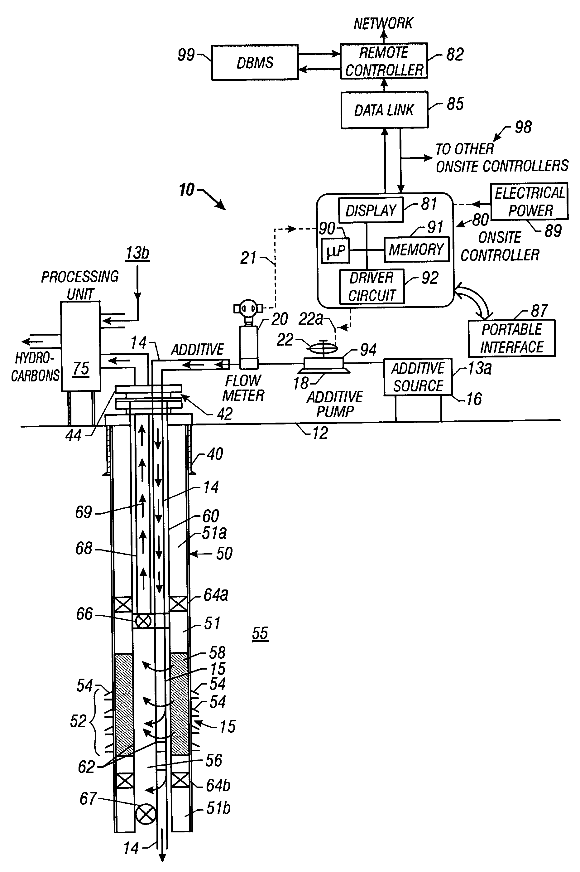
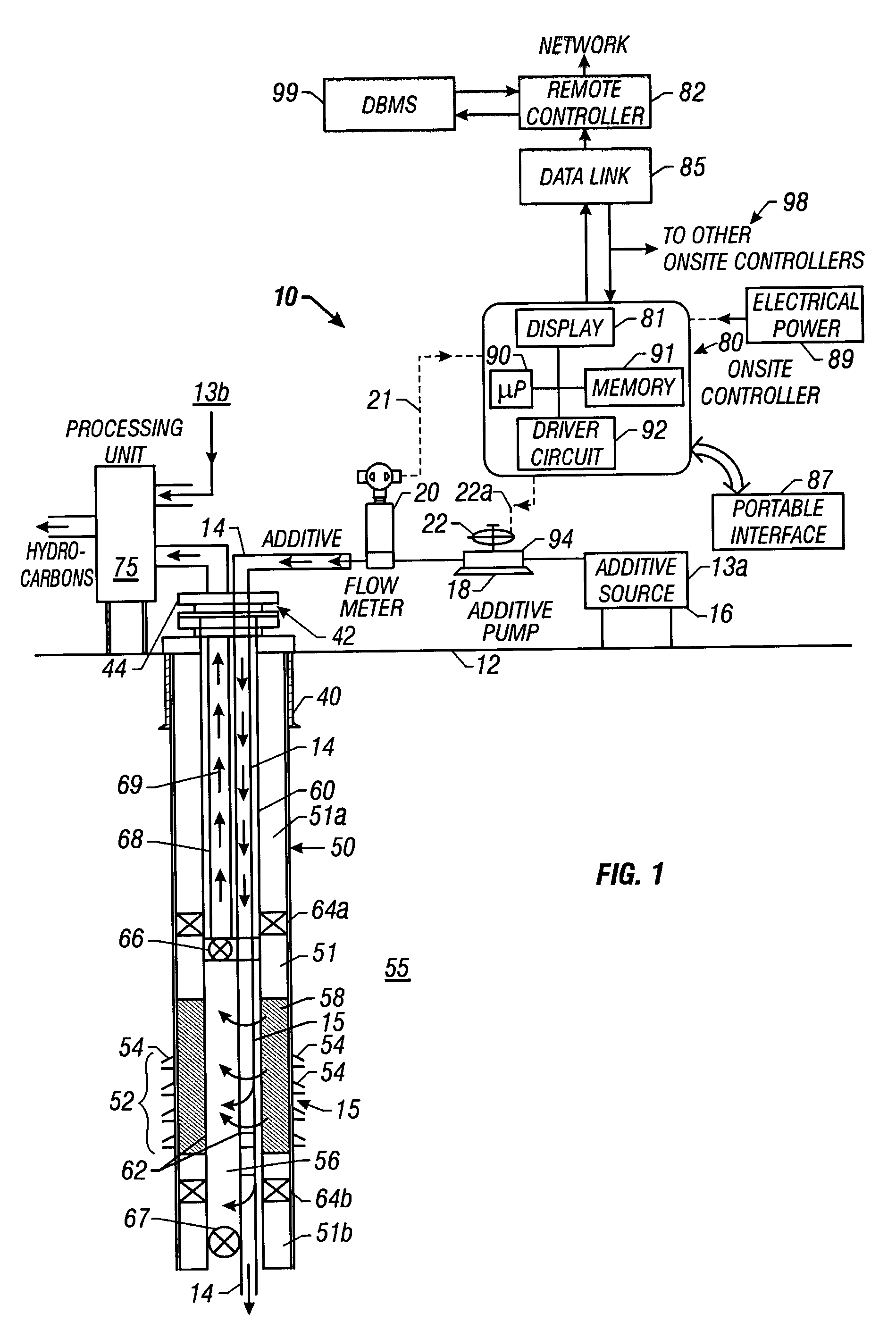
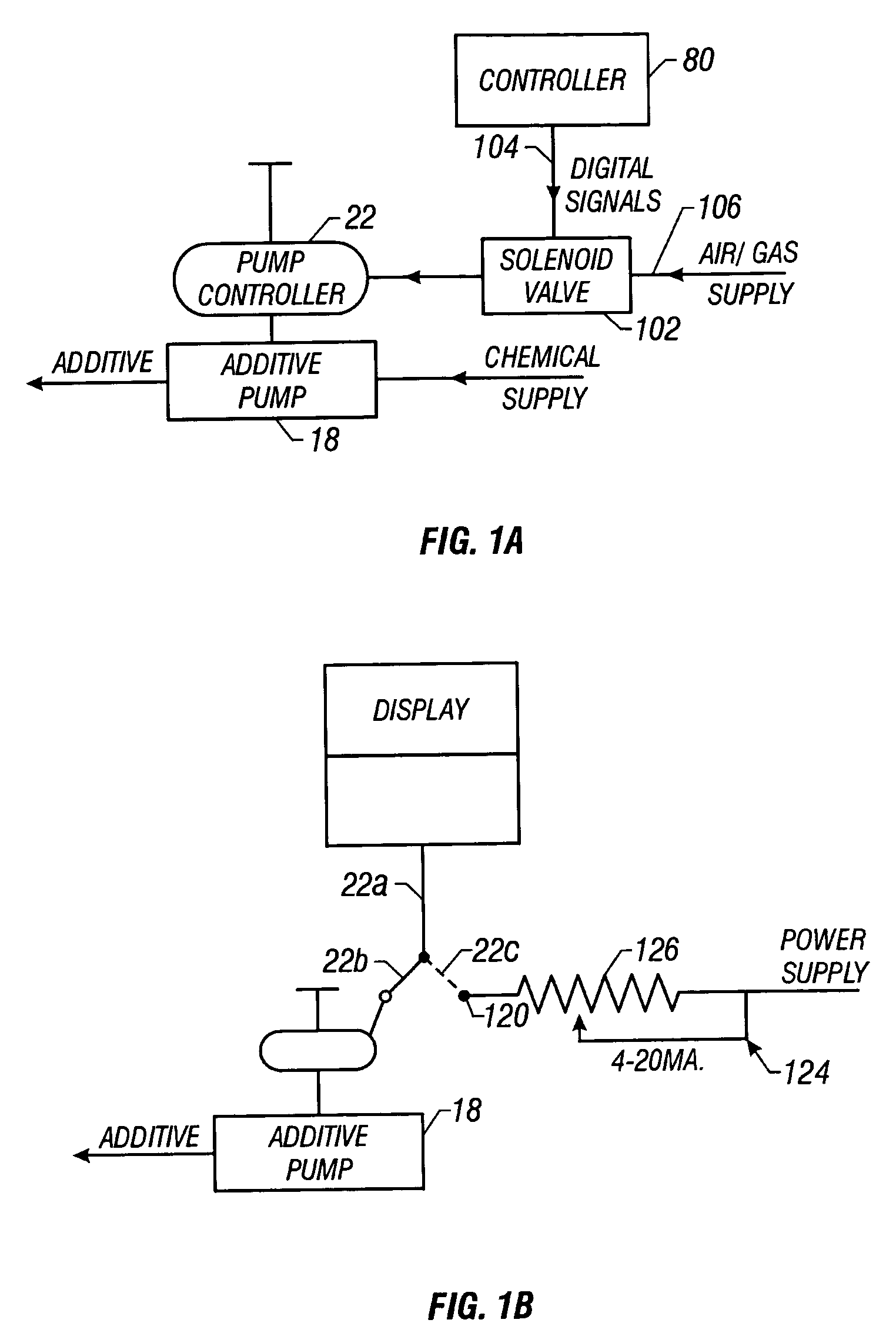
[0018] In one embodiment the present invention provides a wellsite additive injection system that injects, monitors and controls the supply of additives into fluids recovered through wellbores, including with input from remote locations as appropriate. The system includes a pump that supplies, under pressure, a selected additive from a source thereof at the wellsite into the wellbore via a suitable supply line. A flow meter in the supply line measures the flow rate of the additive and generates signals representative of the flow rate. A controller at the wellsite (wellsite or onsite controller) determines from the flow meter signals the additive flow rate, presents that rate on a display and controls the operation of the pump according to stored parameters in the controller and in response to command signals received from a remote location. The controller interfaces with a suitable two-way communication link and transmits signals and data representative of the flow rate and other re...


PUM


Abstract

A system is provided that monitors at the wellsite injection of additives into formation fluids recovered through wellbores and controls the supply of such additives from remote locations. The selected additive is supplied from a source at the wellsite into the wellbore via a suitable supply line. A flow meter in the supply line measures the flow rate of the additive through the supply line and generates signals representative of the flow rate. A controller at the wellsite determines the flow rate from the flow meter signals and in response thereto controls the flow rate of the additive to the well. The wellsite controller interfaces with a suitable two-way communication link and transmits signals and data representative of the flow rate and other parameters to a second remote controller. The remote controller transmits command signals to the wellsite controller representative of any change desired for the flow rate.

Description

RELATED APPLICATIONS [0001] This application is a continuation-in-part of U.S. patent application Ser. No. 09 / 658,907 filed on Sep. 11, 2000; now issued as U.S. Pat. No. 6,851,444; which is a continuation-in-part of U.S. Provisional Patent Application Ser. No. 60 / 153,175 filed on Sep. 10, 1999 and U.S. patent application Ser. No. 09 / 218,067 filed on Dec. 21, 1998 now abandoned.BACKGROUND OF THE INVENTION [0002] 1. Field of the Invention [0003] This invention relates generally to oilfield operations and more particularly to a remotely / network-controlled additive injection system for injecting precise amounts of additives or chemicals into wellbores, wellsite hydrocarbon processing units, pipelines, and chemical processing units. [0004] 2. Background of the Art [0005] A variety of chemicals (also referred to herein as “additives”) are often introduced into producing wells, wellsite hydrocarbon processing units, oil and gas pipelines and chemical processing units to control, among othe...

Claims


Application Information

Patent Timeline
Patent Type & Authority Applications(United States)
IPC IPC(8): E21B37/06E21B41/02E21B43/25
CPCE21B37/06E21B43/25E21B41/02Y10T137/7759Y10T137/0391Y10T137/7761
Inventor MEANS, C. MITCHGREEN, DAVID H.
Owner BAKER HUGHES INC
Learn More