Multi-band feed-forward amplifier and adjustment method therefor
a multi-band, amplifier technology, applied in the direction of amplifier modifications to reduce non-linear distortion, digital transmission, baseband system details, etc., can solve the problems of extreme difficulty in stably maintaining the excellent balance of each distortion detection circuit, and it is difficult to perform simultaneous distortion cancellation
- Summary
- Abstract
- Description
- Claims
- Application Information
AI Technical Summary
Benefits of technology
Problems solved by technology
Method used
Image

Examples
embodiment 1
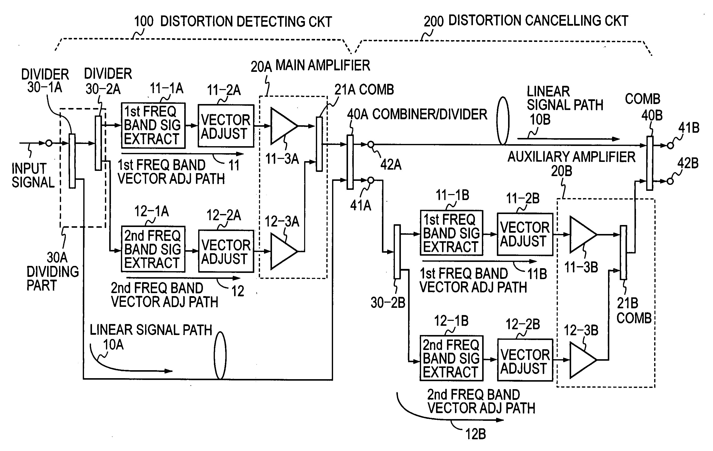
[0076]FIG. 8 illustrates in block form a first embodiment of the feed-forward amplifier according to the present invention. This embodiment uses, as the distortion detecting circuit 100, the multi-band signal processing circuit shown in FIG. 6, the respective parts being denoted by reference numerals added with a suffix “A.” Also this embodiment uses, as the distortion cancelling circuit 200, the multi-band signal processing circuit of FIG. 6, the respective parts being denoted by reference numerals being added with a suffix “B.” The following embodiments of the invention will be described as using two frequency bands for the brevity of description, but in general more than two frequency bands can be used as desired.
[0077] The combining part 40A of the multi-band signal processing circuit forming the distortion detecting circuit 100 is used also as the divider 30-1 (see FIG. 6) in the multi-band signal processing circuit forming the distortion cancelling circuit 200, and hence it f...
embodiment 2
[0086]FIG. 10 illustrates in block form a second embodiment of the feed-forward amplifier according to the present invention. This embodiment uses, as the distortion cancelling circuit 200 in the FIG. 8 embodiment, the multi-band signal processing part shown in FIG. 7. The feed-forward amplifier of this embodiment also makes vector adjustment by use of the vector adjusters 11-2A, 11-2B and 12-2A, 12-2B for the respective frequency bands, and hence it permits compensation for distortion independently for each frequency band. With the vector adjustment paths sufficiently isolated from each other, the adjustment of the vector adjuster for one frequency band does not exert any influence on the vector adjustment of the vector adjuster for the other frequency band. Thus the vector adjusters for multiple frequency bands can be adjusted independently of each other. Simple addition of a required vector adjustment path provides flexibility to the addition of a desired frequency band in which ...
embodiment 3
[0088]FIG. 11 illustrates in block form a third embodiment of the feed-forward amplifier according to the present invention. In this embodiment the multi-band signal processing circuit depicted in FIG. 7 is used as the distortion detecting circuit 100 in the FIG. 8 embodiment. The feed-forward amplifier of this embodiment also makes vector adjustment by use of the vector adjusters 11-2A, 11-2B and 12-2A, 12-2B for the respective frequency bands, and hence it permits compensation for distortion independently for each frequency band.
[0089] Since the main amplifier 20A of the distortion detecting circuit 100 is formed by a single common amplifier 23A that simultaneously amplifies signals of multiple frequency bands as the common amplifier 23 in FIG. 7, it is possible to achieve simplification of the device configuration and power savings from reduction in the number of amplifiers used.
PUM
 Abstract
Description
Claims
Application Information
 - R&D
- Intellectual Property
- Life Sciences
- Materials
- Tech Scout
- Unparalleled Data Quality
- Higher Quality Content
- 60% Fewer Hallucinations
Browse by: Latest US Patents, China's latest patents, Technical Efficacy Thesaurus, Application Domain, Technology Topic, Popular Technical Reports.
© 2025 PatSnap. All rights reserved.Legal|Privacy policy|Modern Slavery Act Transparency Statement|Sitemap|About US| Contact US: help@patsnap.com