Structure of a wave filter
a wave filter and structure technology, applied in the field of wave filters, can solve the problems of ineffective grounding or holding steady of the circuit board, more difficult to properly assemble the wave filter, and inability to effectively ground or hold steady the wave filter, etc., to achieve the effect of effective grounding and convenient fitting in the proper position
- Summary
- Abstract
- Description
- Claims
- Application Information
AI Technical Summary
Benefits of technology
Problems solved by technology
Method used
Image
Examples
first embodiment
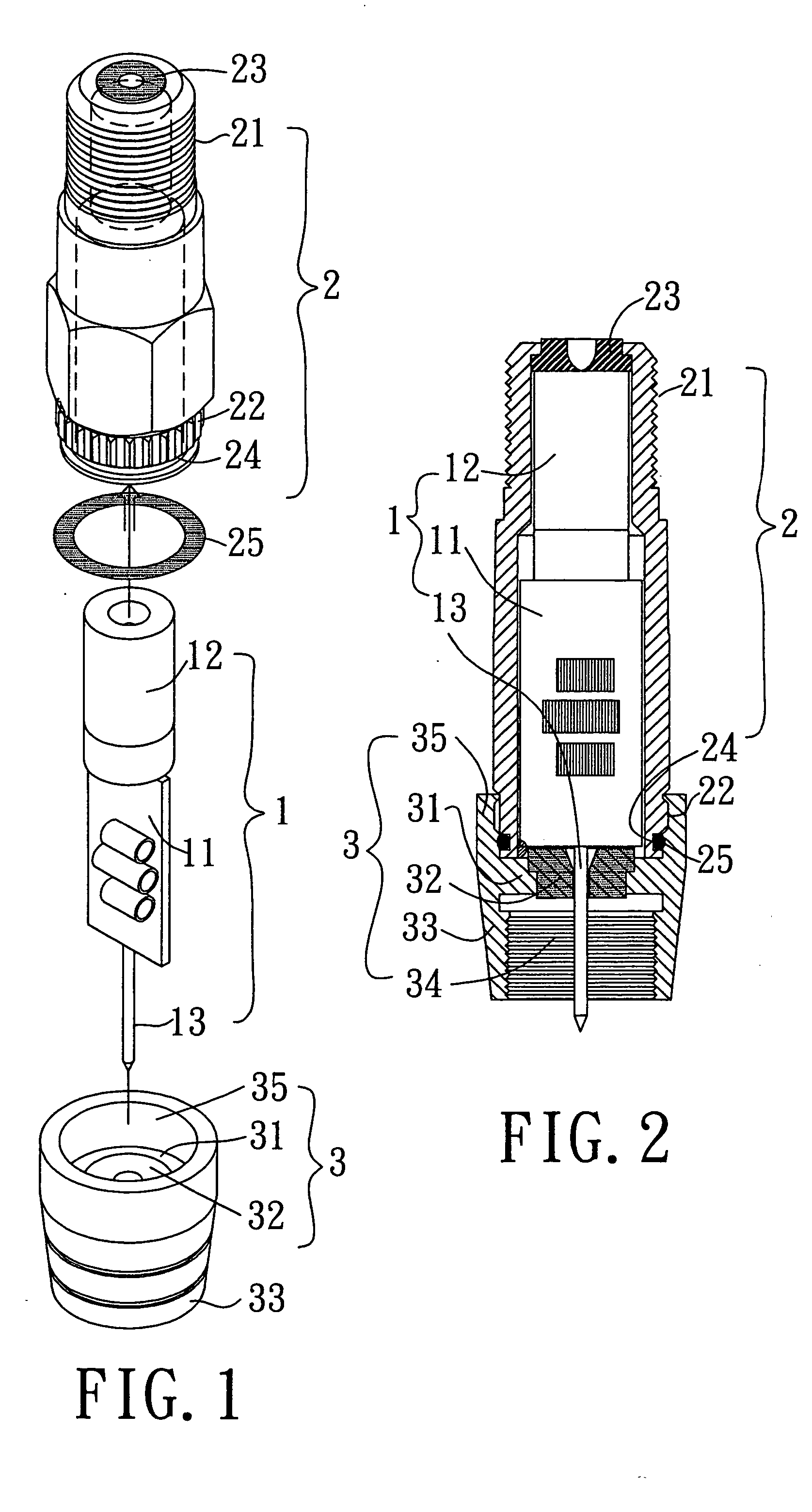
[0022] Referring to FIGS. 1 and 2, a wave filter in the present invention includes a circuit board 1, a metallic holding tube 2, and a metallic cap 3.
[0023] The circuit board 1 includes a substrate 11, electronic parts (not numbered) connected to the substrate 11 by means of solder welding, a connecting head 12 joined to one end of the substrate 11 by means of solder welding, and a lead 13 joined to the other end of the substrate 11 by means of solder welding.
[0024] The holding tube 2 has a first end portion 21, screw threads on an outer side of the end portion 21, an insulating ring 23 fitted in the end portion 21, a fitting end portion 22 at the other end, and an annular groove 24 on an outer side of the fitting end portion 22. The circuit board 1 is held in the holding tube 2 with the connecting head 12 being received in the end portion 21. In addition, a leak-stoppage ring 25 is fitted onto the annular groove 24. The substrate 11 is secured to the inner side of the holding tube...
second embodiment
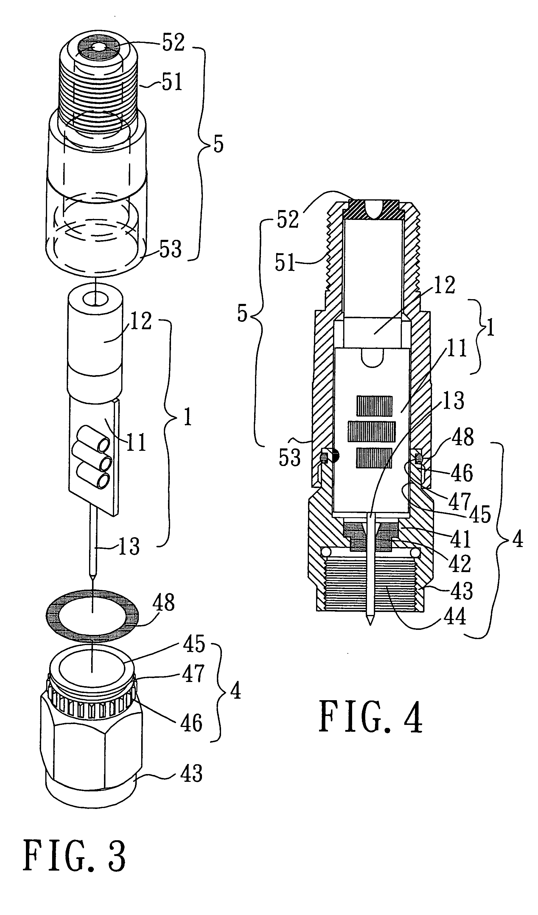
[0027] Referring to FIGS. 3 and 4, a wave filter in the present invention includes a circuit board 1, a metallic holding tube 5, and a metallic cap 4.
[0028] The circuit board 1 includes a substrate 11, electronic parts on the substrate 11, a connecting head 12 joined to one end of the substrate 11 by means of solder welding, and a lead 13 joined to the other end of the substrate 11 by means of solder welding.
[0029] The holding tube 5 has a first end portion 51, screw threads on an outer side of the first end portion 51, an insulating ring 52 fitted in the end portion 21, and a fitting end portion 22 at the other end.
[0030] The cap 4 includes tube-shaped end portions 43 and 45 at two ends. A separating part 41 is disposed between the end portions 43 and 45 of the cap 4, and is secured to an inner side of the cap 4. And, an insulating ring 42 is secured within the separating part 41. The tube-shaped end portion 45 of the cap 4 has a fitting portion 46, whose outer side is formed wit...
PUM
 Abstract
Description
Claims
Application Information
 - R&D
- Intellectual Property
- Life Sciences
- Materials
- Tech Scout
- Unparalleled Data Quality
- Higher Quality Content
- 60% Fewer Hallucinations
Browse by: Latest US Patents, China's latest patents, Technical Efficacy Thesaurus, Application Domain, Technology Topic, Popular Technical Reports.
© 2025 PatSnap. All rights reserved.Legal|Privacy policy|Modern Slavery Act Transparency Statement|Sitemap|About US| Contact US: help@patsnap.com


