
Steering control device and steering control method of motor vehicle

a steering control device and steering control technology, applied in the field of vehicle steering, can solve the problem that the electric power is uselessly consumed for driving the motor of the other system, and achieve the effect of reducing the cost, reducing the cost of the steering control device, and reducing the output specification

Active Publication Date: 2005-07-21
JTEKT CORP
View PDF7 Cites 55 Cited by
  • Summary
  • Abstract
  • Description
  • Claims
  • Application Information

AI Technical Summary

Benefits of technology

[0010] According to the present invention, it can be realized to drive the steering mechanism by the cooperation of the motors of the respective systems when the respective systems are normal. As a result, it can be realized to make the output torque of each motor smaller than that in the prior art, so that the output specification of the motors can be lowered to reduce the cost therefor. This leads to reducing the cost for the steering control device provided with the respective systems.
[0027] According to the present invention, in the normal state, the motors of the respective systems cooperate to drive the steering mechanism. As a result, it can be realized to make the output torque of each motor smaller than that in the prior art, so that the output specification of the motor can be lowered to reduce the cost therefor. This leads to reducing the cost for the steering control device provided with the respective systems.

Problems solved by technology

Thus, there arises a problem that an electric power is uselessly consumed for driving the motor of the other system which actually does not drive the shaft in the normal state.

Method used


Image

  • Steering control device and steering control method of motor vehicle
  • Steering control device and steering control method of motor vehicle
  • Steering control device and steering control method of motor vehicle

Examples


Embodiment Construction

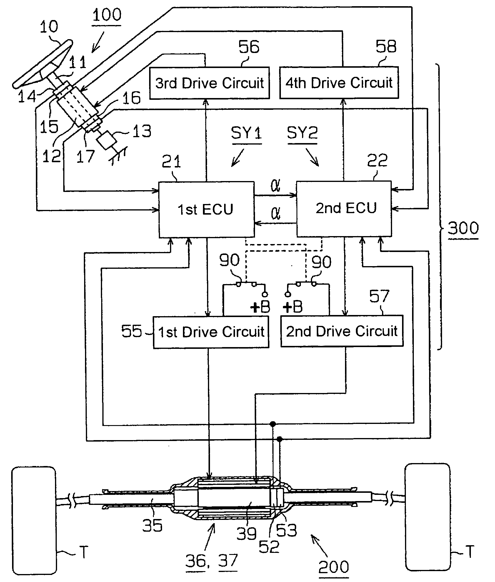
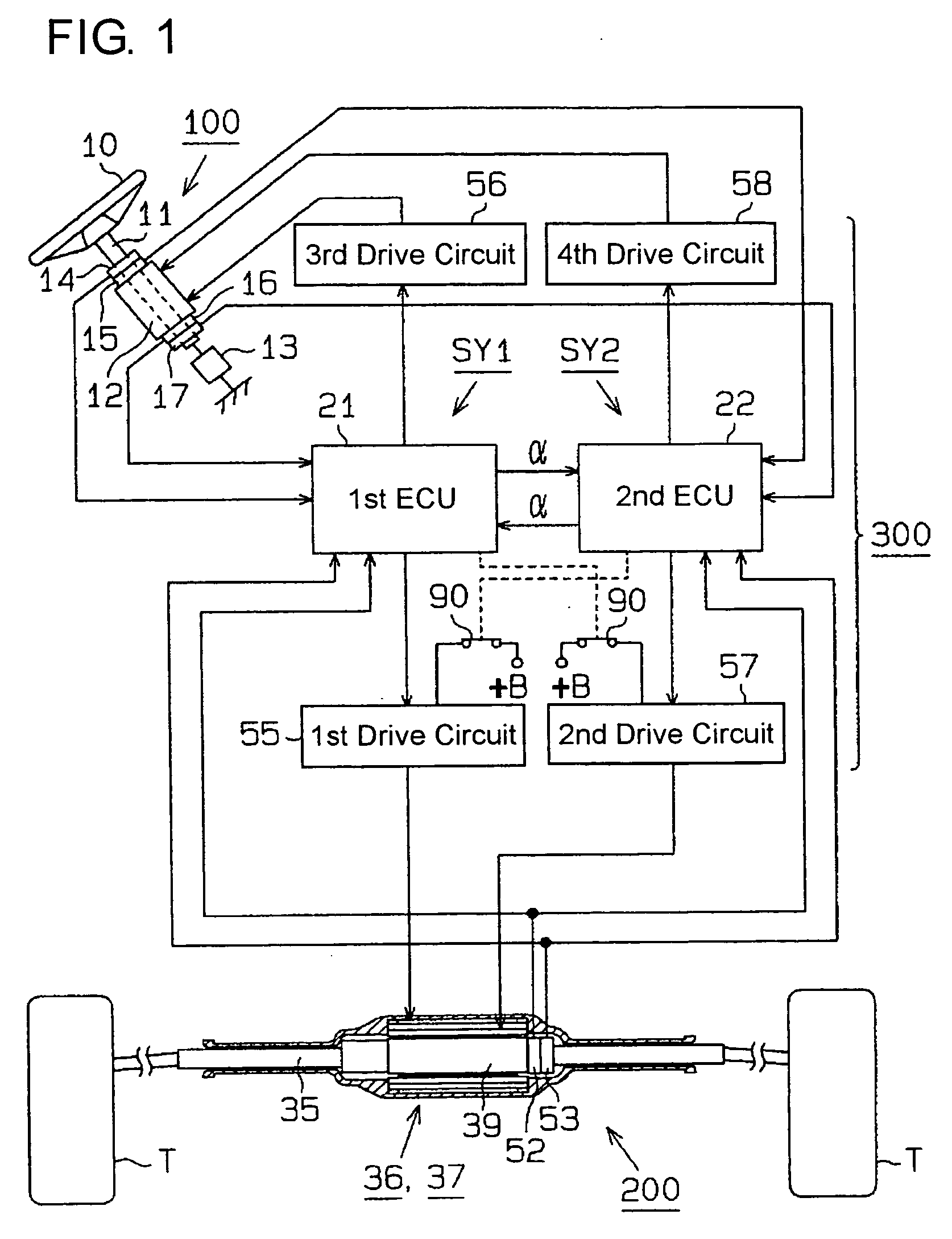
[0035] Hereafter, one embodiment of a steering control device of the steer-by-wire type (hereafter referred simply as “steering control device”) according to the present invention which is incorporated in a vehicle will be described in detail with reference to FIGS. 1 to 7. FIG. 1 shows a conceptual illustration of the steering control device in the present embodiment. The steering control device is provided with a manipulation mechanism 100 including a steering wheel 10 (steering handle), a steering mechanism 200 and a control section 300.

[0036] (Manipulation Mechanism 100)

[0037] The steering wheel 10 of the manipulation mechanism 100 is connected to a rotational shaft 11 rotatably carried on a vehicle (not shown). A reaction force exerting motor 12 is provided against the rotational shaft 11 and exerts a steering reaction force on the steering wheel 10. The reaction force exerting motor 12 is composed of a drive motor (e.g., brushless DC motor) with an output shaft thereof integ...


PUM


Abstract

A first system and a second system include a first motor and a second motor for driving a steering mechanism in dependence on the rotational manipulation of a steering wheel. A first ECU and a second ECU mutually monitor abnormalities of the systems each to stop an abnormal system. When the respective systems are normal, the first ECU and the second ECU drivingly control the first motor and the second motor of their own systems to drive the steering mechanism by cooperation of the respective motors. When either one of the both systems is abnormal, the ECU of the other system solely drivingly controls the motor of its own system thereby to drive the steering mechanism. Thus, it can be realized to make the systems low in cost irrespective of the provision of the plural systems.

Description

TECHNOLOGICAL FIELD [0001] The present invention relates to a vehicle steering control device and a vehicle steering control method used in a steering control device of the steer-by-wire type or an electric power steering control device. BACKGROUND ART [0002] As devices for controlling steerable wheels for vehicles, there has heretofore been known a steering control device of the steer-by-wire type that a steering wheel is mechanically disconnected from a steering gear box which is in linkage to front wheels (steerable wheels). In the steering control device, the steering wheel is not mechanically connected to the steering gear box, and the steering angle of the steering wheel is detected so that the steering gear box is driven by an electric motor in dependence on the detected steering angle. [0003] In the steering control device of this kind, a fail-safe capability of a certain type is provided so that the steering operation is enabled to be continued reliably in the event of a fa...

Claims


Application Information

Patent Timeline
Patent Type & Authority Applications(United States)
IPC IPC(8): B62D6/00B62D5/00B62D5/04B62D113/00B62D119/00B62D137/00H02K16/04H02K29/00H02P6/12H02P6/16
CPCB62D5/003
Inventor TAKEUCHI, SHINJINAKANO, JIROFUKUMURA, KENICHIMORI, YUTAKA
Owner JTEKT CORP
Learn More