
Catheter system for delivery of therapeutic compounds to cardiac tissue

a catheter system and cardiac tissue technology, applied in the field of catheter system for delivery of therapeutic compounds to cardiac tissue, can solve the problems of significant morbidity and mortality, large cardiac tissue death or myocardial infarction region, and defect in an important part of the conduction system

Inactive Publication Date: 2005-07-21
LESH MICHAEL D
View PDF84 Cites 31 Cited by
  • Summary
  • Abstract
  • Description
  • Claims
  • Application Information

AI Technical Summary

Benefits of technology

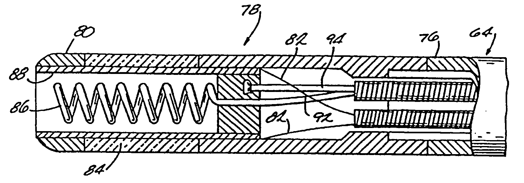
[0015] The tissue ablation assembly comprises a hollow infusion needle which can be extended or withdrawn from the distal end of the catheter. The hollow infusion needles of the invention have a securing element configured to engage tissue when the needle is at least partially inserted into the tissue to stop recoil and help prevent inadvertent removal of the needle from the tissue. The securing element can be configured into the form of corkscrew or threads surrounding a straight needle. Alternatively, the securing element can be configured as a plurality of pre-curved needles, which curve towards or away from the longitudinal axis of the catheter. The pre-curved needles can also be used to deliver ablation compounds of desired. Other structures, such as barbs, could also be used as the securing element. The hollow infusion needle is preferably a corkscrew-shaped needle, with a tight curl. The distance between turns is preferably about 0.5 mm or less. Such a needle allows the practitioner to inject through layers by slowly extending the needle, injecting, extending farther and injecting again.

Problems solved by technology

Abnormal heart beats or cardiac arrhythmias can cause significant morbidity and mortality.
Similarly, a defect can exist in an important part of the conduction system such as the bundle of His or one of the bundle branches supplying the ventricles.
Unfortunately this tends to result in a fairly large region of cardiac tissue death or myocardial infarction.
With transarterial infusion there is difficulty in precisely controlling the location and extent of the ablation.

Method used


Image

  • Catheter system for delivery of therapeutic compounds to cardiac tissue
  • Catheter system for delivery of therapeutic compounds to cardiac tissue
  • Catheter system for delivery of therapeutic compounds to cardiac tissue

Examples


Embodiment Construction

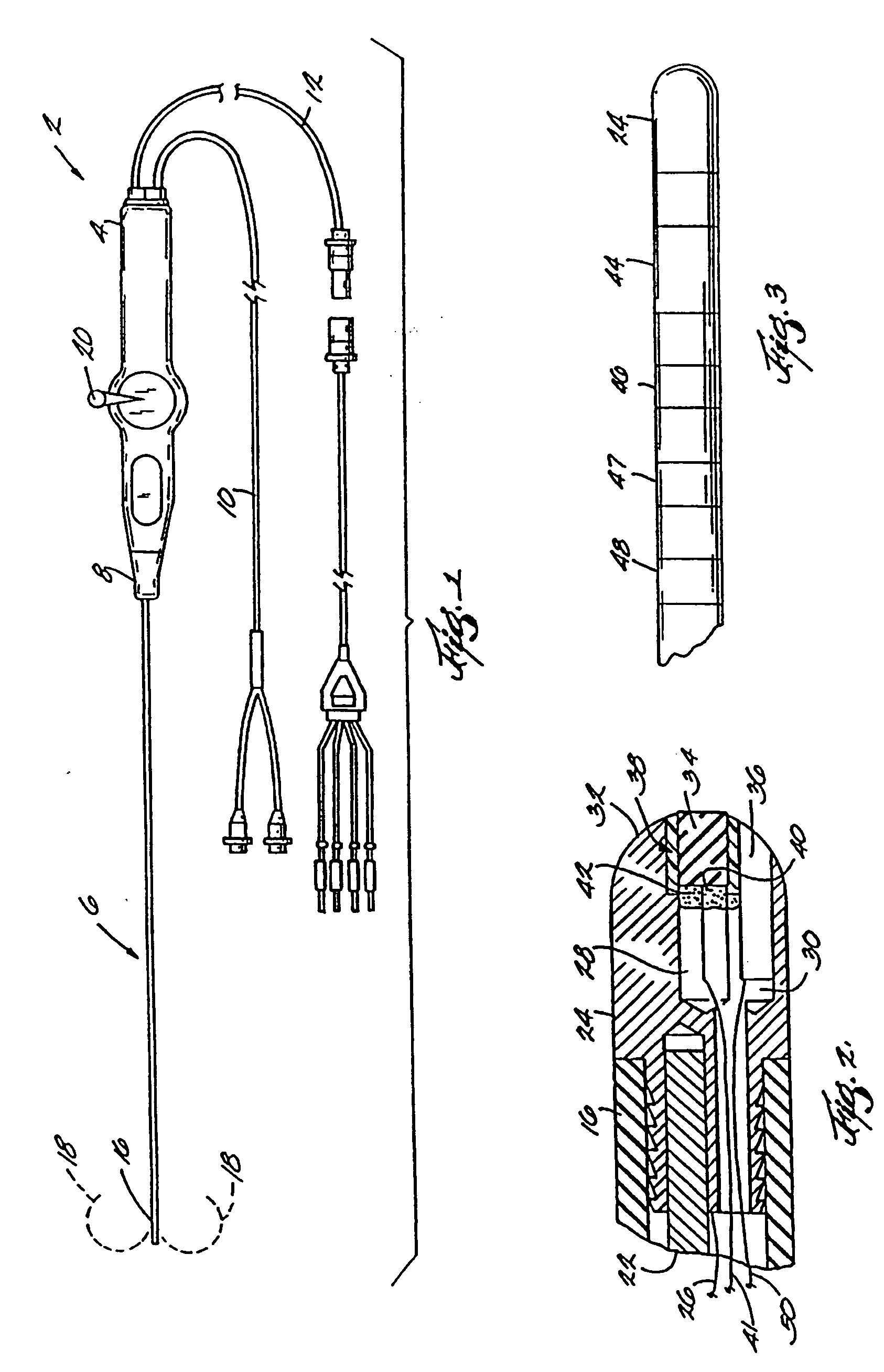
[0040]FIG. 1 illustrates a catheter 2 having a handle 4 from which a flexible body 6 extends. Flexible body 6 extends from one end 8 of handle 4 while ultrasonic cable 10 and a combination electrode / thermistor cable 12 extend from the other end 14 of handle 4. Distal end 16 of flexible body 6 is steerable, as suggested by the dashed lines 18 in FIG. 1, in a conventional manner using a steering lever 20 mounted to handle 4. Lever 20 which controls one or more steering cables 22, see FIG. 2, as is conventional. Distal end 16 has an RF transmitting tip 24 secured thereto. Transmitting tip 24 is connected to an appropriate RF energy source, not shown, through lead 26 which extends along flexible body 6, through handle 4 and through combined cable 12.

[0041] Tip 24 has a pair of axially extending bores 28,30 formed from its distal end 32. Bore 28 is used to house an ultrasonic transducer 34 while bore 30 is used to house a thermistor 36. Transducer 34 is surrounded by a thermal insulatin...


PUM


Abstract

This is a method and an apparatus for the treatment or introduction of contrast fluids into tissue, particularly cardiac tissue. The apparatus includes a catheter having an elongated flexible body and a tissue infusion apparatus including a hollow infusion needle configured to secure the needle into the tissue when the needle is at least partially inserted into the tissue to help prevent inadvertent removal of the needle from the tissue. This permits the selected treatment or contrast fluid to be confined to a specific site. The catheter may also include a visualization assembly including a transducer at the distal end of the body.

Description

CROSS-REFERENCE TO RELATED APPLICATIONS [0001] This application is a continuation of U.S. Ser. No. 08 / 403,553, filed Mar. 14, 1995, which in turn is a continuation of U.S. Ser. No. 08 / 100,086, filed Jul. 30, 1993, the contents of both are hereby incorporated by reference into the present disclosure.BACKGROUND OF THE INVENTION [0002] Abnormal heart beats or cardiac arrhythmias can cause significant morbidity and mortality. These arrhythmias arise from a variety of causes, including atherosclerotic heart disease, ischemic heart disease, metabolic or hemodynamic derangements, rheumatic heart disease, cardiac valve disease, certain pulmonary disorders and congenital etiologies. The normal heart rate is about 60 to 100 beats per minute. Arrhythmias refer to tachycardias at rates exceeding 100 beats per minute for a duration of at least 3 beats. Sometimes no treatment is required, such as in the tachycardia following a physiologic response to stress or exercise. However, in some cases, tr...

Claims


Application Information

Patent Timeline
IPC IPC(8): A61B17/00A61B17/22A61B17/34A61B19/00A61M25/00A61M25/01
CPCA61B17/22A61B2017/00243A61B2017/22082A61B2017/3488A61B2018/00273A61B2018/00815A61N7/02A61B2018/1435A61B2019/528A61M25/0084A61M25/0133A61M25/0136A61M25/0147A61B2018/1425A61B2090/3784
Inventor LESH, MICHAEL D.
Owner LESH MICHAEL D
Learn More