
Disk device

a technology of a disk and a storage device, which is applied in the direction of recording information storage, electrical apparatus construction details, instruments, etc., can solve problems such as the broken container

Inactive Publication Date: 2005-07-21
KK TOSHIBA
View PDF5 Cites 14 Cited by
  • Summary
  • Abstract
  • Description
  • Claims
  • Application Information

AI Technical Summary

Benefits of technology

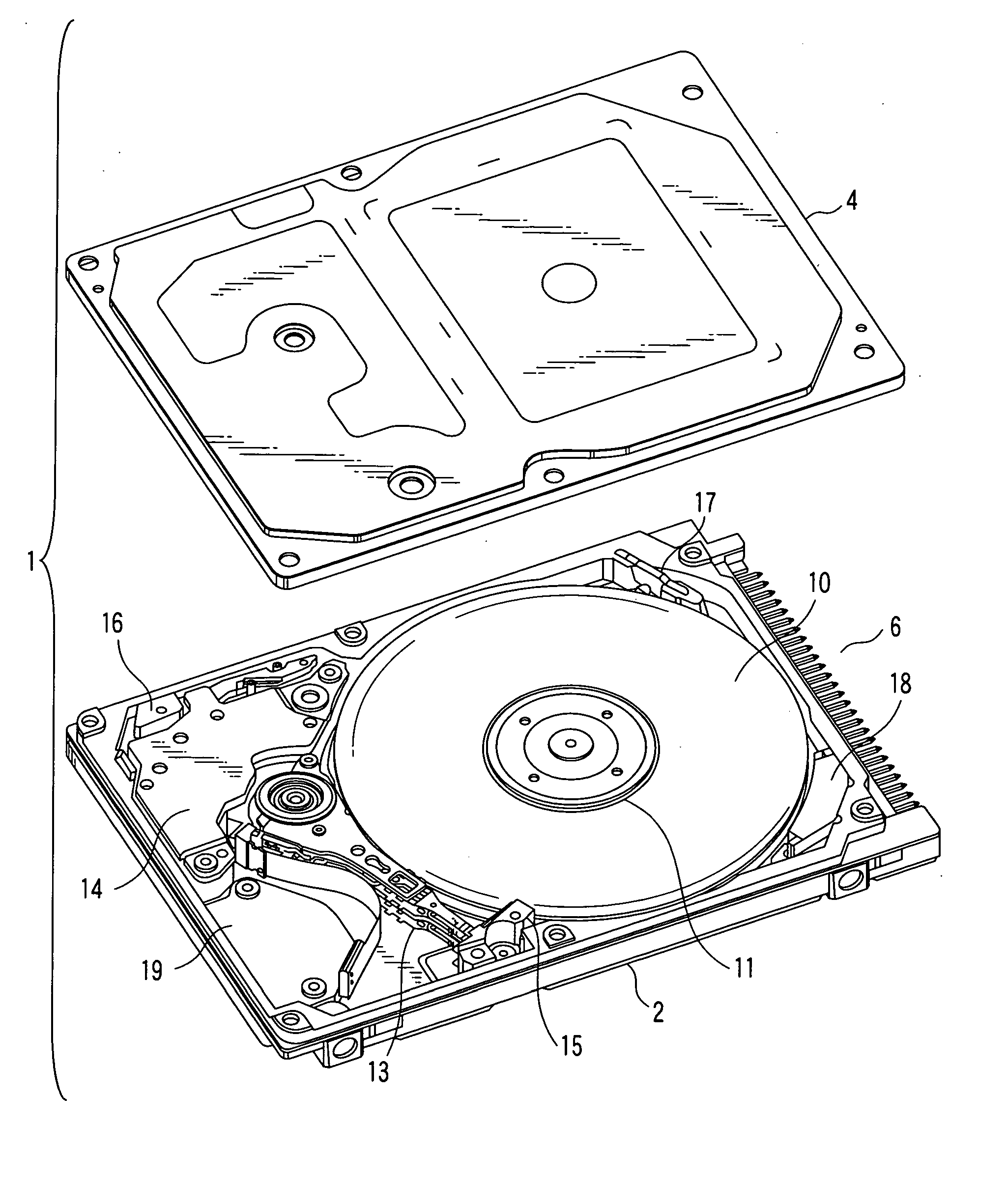
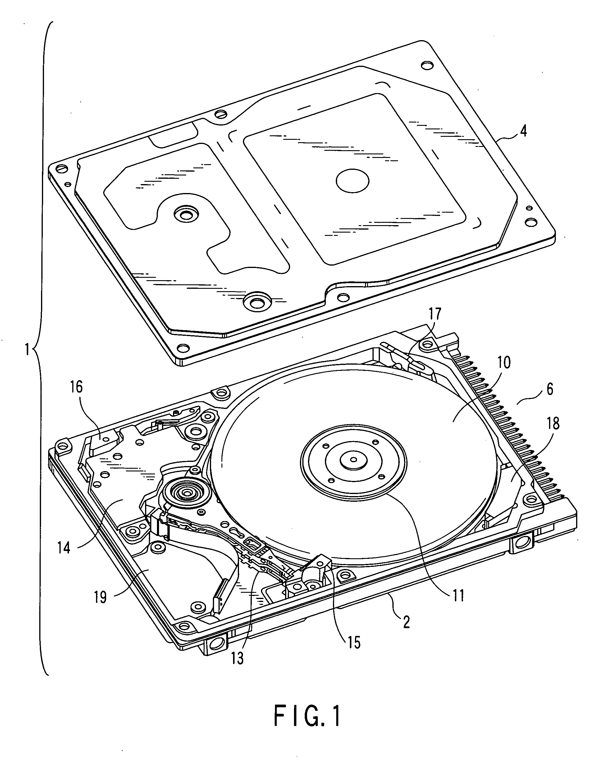
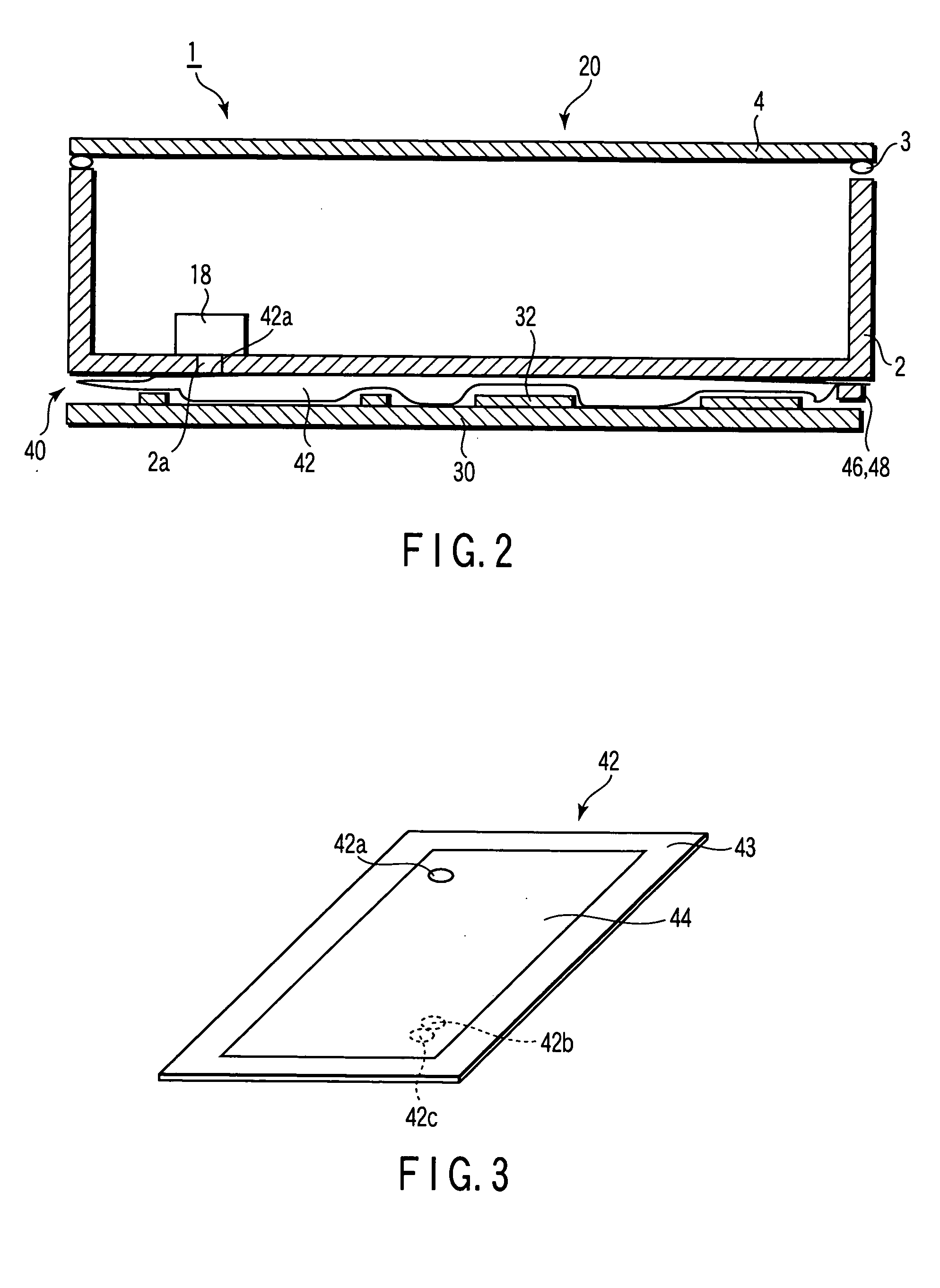
The present invention provides a disk device with an air intake and exhaust mechanism that can be accommodated in a small space and still fulfill its intended function. The device includes a disk unit, a circuit board, and a flat bag between the disk unit and the circuit board. The flat bag has a communication hole that can compensate for changes in the internal air pressure of the housing. The device also includes air intake and exhaust valves that can take in and exhaust outside air. The flat bag acts as a heat insulator, absorbing vibration and sound. Overall, the invention provides a compact and efficient air intake and exhaust mechanism for disk devices.

Problems solved by technology

However, in the above device, it is necessary to provide space for attaching the bellows-shaped expandable container to the outer surface of the housing.
Furthermore, when variation of the air pressure in the housing exceeds the tolerable limit of the bellows-shaped expandable container, the container is broken.

Method used


Image

  • Disk device
  • Disk device
  • Disk device

Examples


example 1

[0042] In example 1, two polypropylene sheets each having a thickness of 100 μm, a width of 15 mm and a length of 80 mm were prepared. A communication hole 42a was formed close to one of the short sides of one of the sheets, and holes 42b and 42c for provision of an intake valve 46 and an exhaust valve 48 were formed close to the other short side. In this case, it should be noted that the holes 42b and 42c do not need to be separated from each other. That is, they may be formed continuous with each other. In addition, they may be formed in the other of the above sheets.

[0043] Then, an annular seal portion was provided in such a manner as to surround the communication hole 42a, and the intake valve 46 and the exhaust valve 48 each having the above structure were provided at the holes 42b and 42c.

[0044] Then, the sheets were stacked together, and seal portions 43 each having a width 3 mm were provided at peripheral portions of the sheets. The seal portions 43 of the sheets were heat...

example 2

[0052] The following adsorptive sheet was prepared: a hole having a diameter of 35 mm was formed in a center portion of a rectangular activated charcoal sheet having a size of 50 mm×50 mm. In example 2, a cloth absorbent sheet (model: CC-507) made by Kynol Inc. was used as an activated charcoal sheet. Needless to say, the adsorptive sheet is not limited to the cloth absorbent sheet. That is, any sheet may be used as the adsorptive sheet as long as it is flexibly formed such that it can be sealed in a bag 42 of an air intake and exhaust mechanism 40. For example, any of the following sheets can be used: a sheet in which coconut palm grain activated charcoal particles having a particle size of approximately 50 μm are adhered to an adhesive sheet having a desired shape; and a sheet in which kinds of binder fibers representative of kinds of Teflon-based fibers are mixed.

[0053] Furthermore, two polypropylene sheets having a thickness of 100 μm and a size of 60 mm×60 mm were prepared, wh...


PUM

PropertyMeasurementUnit
thicknessaaaaaaaaaa
pressureaaaaaaaaaa
air pressureaaaaaaaaaa

Abstract

A HDD includes a disk unit, a circuit board and an air intake and exhaust mechanism. In the disk unit, a magnetic disk is rotatably provided. The circuit board is provided with a driving circuit including electronic components. The air intake and exhaust mechanism includes a bag provided between the disk unit and the circuit board. The bag includes a communication hole airtightly communicating with an air intake and exhaust hole provided in a housing of the disk unit, and air intake and exhaust valves are provided at the bag, and located apart from the communication hole. Due to this structure, when the internal air pressure of the disk unit changes, gas flows into and out from the gap between the disk unit and the bag through the communication hole, thus restricting changing of the air pressure.

Description

CROSS-REFERENCE TO RELATED APPLICATIONS [0001] This application is based upon and claims the benefit of priority from prior Japanese Patent Application No. 2004-010807, filed Jan. 19, 2004, the entire contents of which are incorporated herein by reference. BACKGROUND OF THE INVENTION [0002] 1. Field of the Invention [0003] This invention relates to a disk device provided with an air intake and exhaust mechanism for restricting changing of the internal air pressure of a housing. [0004] 2. Description of the Related Art [0005] As a conventional disk device including an air intake and exhaust mechanism, for example, the following device is well known: a bellows-shaped expandable container is attached to an outer surface of a filter which is provided at the housing of the device (as disclosed in, e.g., Jpn. Pat. Appln. KOKAI Publication No. 3-266285). The container expands / contracts in accordance with variation of the internal air pressure of the housing, and thus prevents the outside a...

Claims


Application Information

Patent Timeline
Patent Type & Authority Applications(United States)
IPC IPC(8): G11B25/04G11B33/00G11B33/08G11B33/12G11B33/14
CPCG11B33/1486G11B33/121
Inventor HATANAKA, TATSUYA
Owner KK TOSHIBA
Learn More