
Two speed transmission and belt drive system

a transmission system and belt drive technology, applied in mechanical equipment, transportation and packaging, gearboxes, etc., can solve the problems of less than the optimal efficiency of most of the engine speed range, inefficient operation of accessories, and relatively high speed of accessories, and achieve the effect of greater speed

Active Publication Date: 2005-07-14
THE GATES CORP
View PDF45 Cites 45 Cited by
  • Summary
  • Abstract
  • Description
  • Claims
  • Application Information

AI Technical Summary

Benefits of technology

[0015] The invention comprises a two speed transmission and belt drive system utilizing the transmission. The two speed transmission comprises a planetary gear train comprising an input pulley connected to an input carrier, and a sun gear and a ring gear. The input carrier also comprises a plurality of planetary gears disposed between the sun gear and the ring gear. The sun gear is engaged with an electromagnetic brake member. The ring gear is engaged with an output pulley. A one-way clutch is disposed between the input carrier and the output shaft. The brake member is engaged at engine idle and is disengaged at engine speeds above idle. When the brake member is engaged the su

Problems solved by technology

The variations in engine speed, particularly engine speeds greater than idle, result in inefficient operation of the accessories because each accessory must be designed to operate satisfactorily over the entire engine speed range.
This necessarily means that the efficiency is less than optimum for most of the engine speed range.
Further, operating the accessories at relatively higher speeds places a greater load on the engine than if they are operated at a slower speed.
Such a system can be adversely affected by loss of vacuum, for example by vacuum hose failure, or by contamination on the cylindrical surface between the brake band and the cylindrical surface.

Method used


Image

  • Two speed transmission and belt drive system
  • Two speed transmission and belt drive system
  • Two speed transmission and belt drive system

Examples


Embodiment Construction

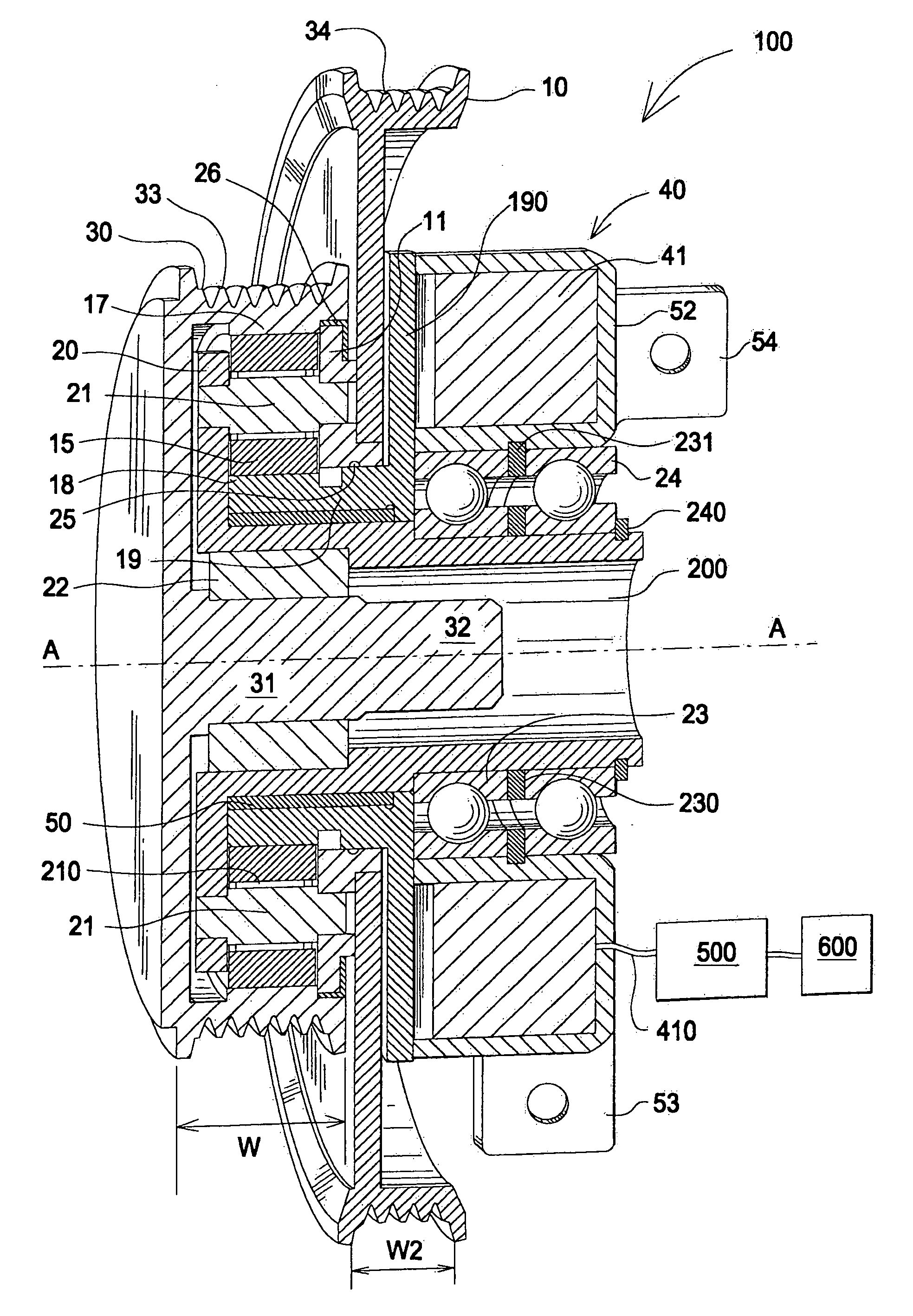
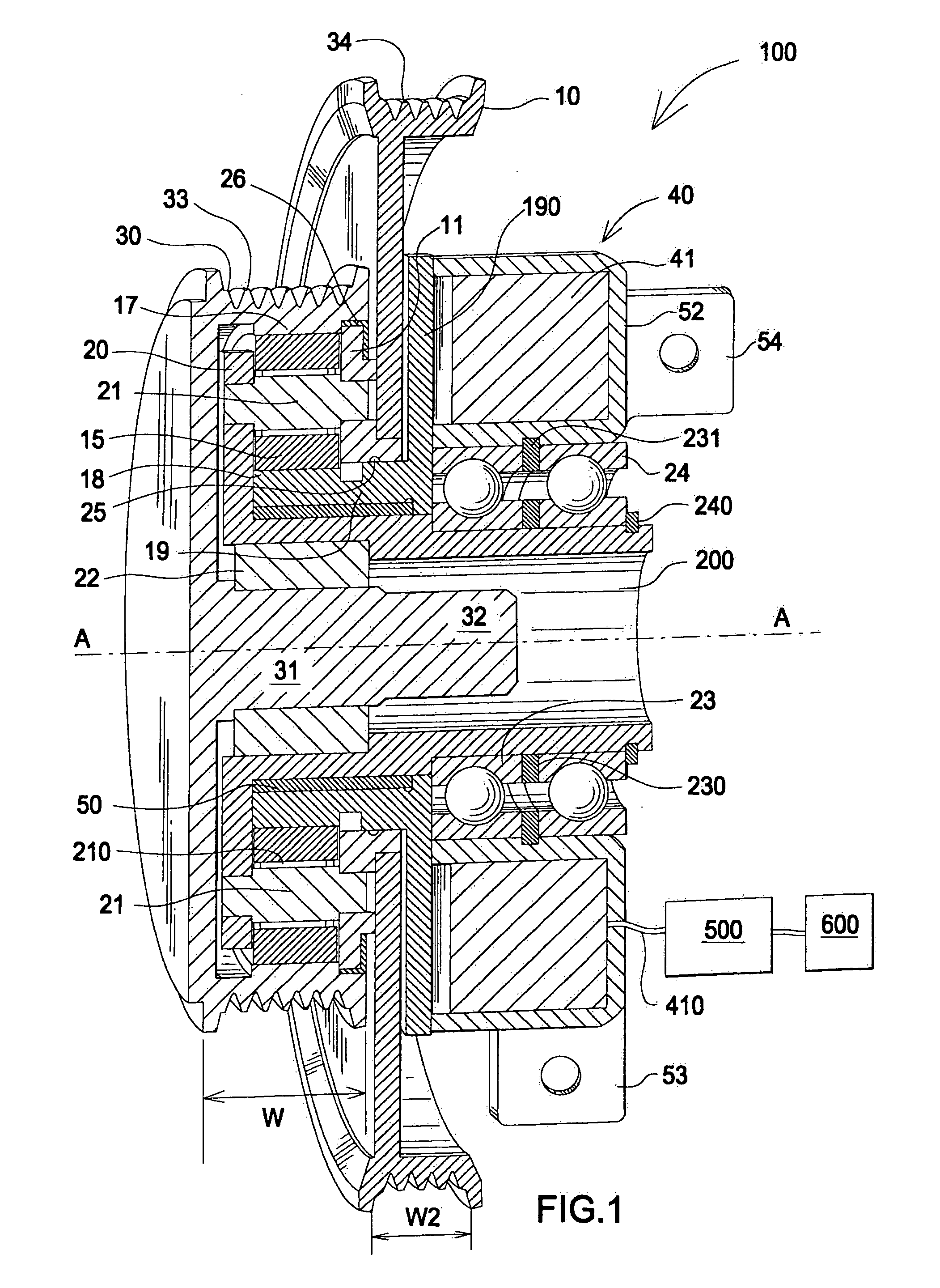
[0031]FIG. 1 is a cross-sectional view of the two speed transmission. The two speed transmission 100 is used on a belt driven accessory drive of the type used on vehicle internal combustion engines. It may also be used in any application where a two speed transmission is needed, for example, for driving industrial equipment or as a transmission on a 2, 3 or 4 wheeled vehicle.

[0032] The transmission and associated control system automatically control an accessory speed based on engine speed in order to optimize engine fuel efficiency and available output drive torque at the drive wheels. The transmission is very compact and can be mounted directly on an accessory, for example on a power steering pump, alternator or air conditioner compressor. In this arrangement the accessory is connected to an engine block.

[0033] The two speed transmission 100 comprises planetary gears disposed on an input carrier. The transmission input shaft and output shaft are coaxial. An electromagnetic brake...


PUM


Abstract

A two speed transmission and belt drive system utilizing the transmission. The two speed transmission comprises a planetary gear train comprising an input pulley connected to an input carrier, and a sun gear and a ring gear. The input carrier also comprises a plurality of planetary gears disposed between the sun gear and the ring gear. The sun gear is engaged with an electromagnetic brake member. The ring gear is engaged with an output pulley. A one-way clutch is disposed between the input carrier and the output shaft. The brake member is engaged at engine idle and is disengaged at engine speeds above idle. When the brake member is engaged the sun gear does not rotate, thereby driving the ring gear and output pulley at a greater speed than the input pulley. An accessory pulley operates with the transmission output pulley resulting in an accessory speed that is proportional to an engine speed at idle. At engine speeds above idle the transmission is disengaged and the output pulley to accessory pulley ratio drives the belt driven accessory at a speed less then an engine speed. An accessory can also be directly connected to the output shaft in conjunction with the output pulley. The transmission can be used with a motor generator system by providing a speed reducing unit disposed between an engine and the motor generator.

Description

FIELD OF THE INVENTION [0001] The invention relates to a two speed transmission and belt drive system, more particularly, to a vehicle engine belt drive system using a combination of accessory pulleys and a two speed transmission having an electromagnetic brake. The two speed transmission output pulley in combination with each accessory pulley drives engine accessories at a first speed substantially proportional to an engine speed at engine idle and proportionally less than the first engine speed for those engine speeds substantially greater than an engine idle speed. The transmission also provides a speed reducing unit disposed between an engine and a motor generator. BACKGROUND OF THE INVENTION [0002] Vehicle engines generally comprise certain accessories that are used in the operation of the engine and vehicle. Such accessories can include a power steering pump, an air conditioning compressor, an alternator, an oil pump, a fuel pump and so on. These accessories are generally driv...

Claims


Application Information

Patent Timeline
IPC IPC(8): B60K25/00H02K7/10
CPCB60K25/00Y10T477/688H02K7/1004B60K2006/4833B60K6/48B60K25/02
Inventor SERKH, ALEXANDER
Owner THE GATES CORP
Learn More