Motor state counting

a technology of motor state and counting, applied in the direction of counting objects on conveyors, electronic commutators, instruments, etc., can solve problems such as faulty commutation and degradation of motor performan

Active Publication Date: 2005-07-14
HR TEXTRON
View PDF6 Cites 22 Cited by
  • Summary
  • Abstract
  • Description
  • Claims
  • Application Information

AI Technical Summary

Benefits of technology

[0013] A second embodiment may include a method of incrementing a position counter including the steps of detecting an indicated Hall state from a plurality of digital Hall effect sensors and detecting a duration of the indicated Hall state. The duration may be compared to a specified time period and the indicated Hall may be compared to one or more valid Hall states, in the event that the duration is greater than the specified time period. A step of determining whether the indicated Hall state corresponds to a valid Hall state may be included. The indicated Hall state may be determined to correspond to a first direction or a second direction relative to a previous Hall state. A position counter may be changed in response to determining that the indicated Hall state corresponds to the first direction or the second direction. The indicated Hall state may be ignored, in the event that the indicated Hall state corresponds to an invalid Hall position or the duration is less than the specified time per...

Problems solved by technology

When digital Hall sensors are used for motor position feedback and commutation, a noise-induced Hall state transiti...

Method used


Image

  • Motor state counting
  • Motor state counting
  • Motor state counting

Examples


Embodiment Construction

[0026] The present invention may be understood by the following detailed description, which should be read in conjunction with the attached drawings. The following detailed description of certain embodiments is by way of example only and is not meant to limit the scope of the present invention.

[0027] Embodiments of the present invention are directed to methods, computer-readable media, and systems for noise-compensated or error-compensated counting of Hall states for motor position feedback and / or commutation in brushless DC motor applications.

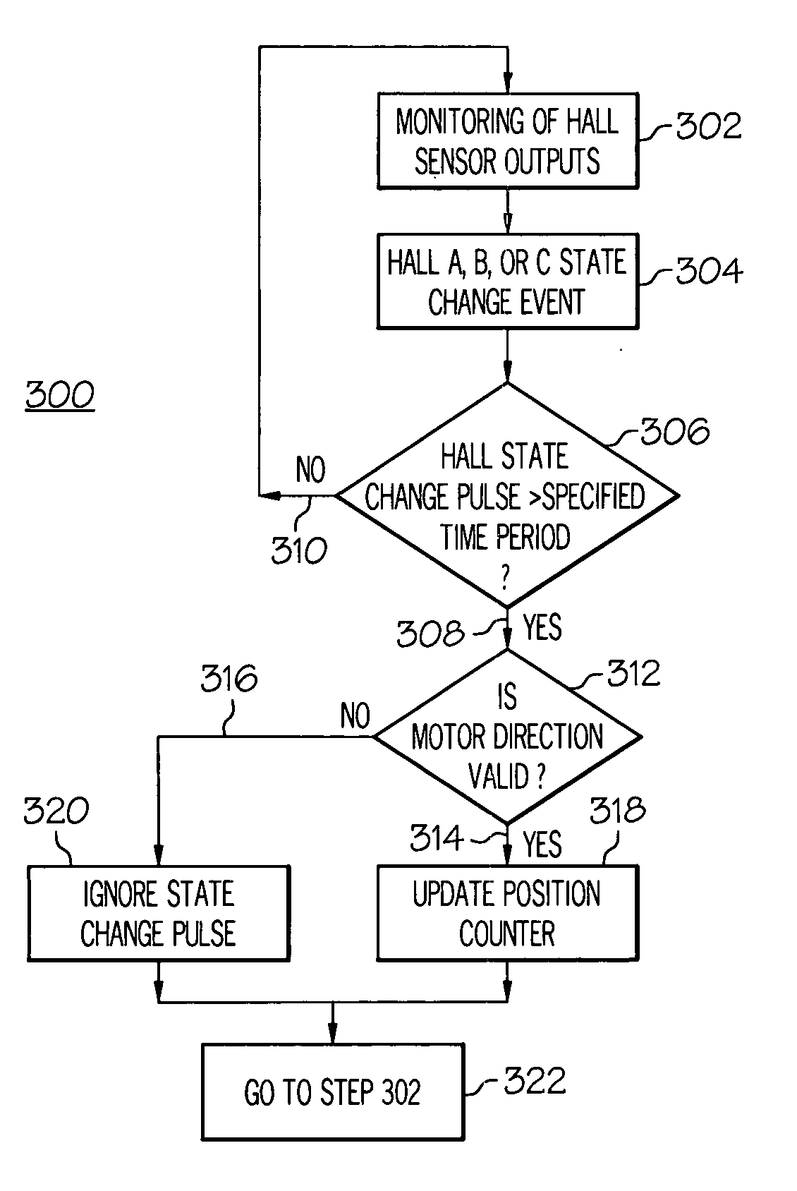
[0028]FIG. 3 includes FIGS. 3A and 3B, which are flow charts for a motor state counting method 300 according to embodiments of the present invention. With reference to FIG. 3A, a combined digital Hall sensor output including digital Hall states produced by a number of digital Hall sensors used with a brushless DC motor may be periodically monitored 302 for a change in value or state to determine whether a Hall state transition or Hall state ...


PUM


Abstract

Systems, methods, and computer-readable media are disclosed for error-compensated counting of Hall states for motor position feedback and/or commutation. An indicated Hall state is detected by digital Hall state sensors and a duration of the Hall state is compared to a specified time period. When the duration exceeds the specified time period, the indicated Hall state is compared to one or more valid Hall states and a position counter is changed for valid states. When the indicated Hall state is invalid, the position counter is not changed. The Hall state sensors may be connected to logic means and may detect the position of a rotor of a permanent magnet motor relative to a stator. When noise induces a change in an indicated Hall state, corresponding noise-induced effects on the position counter may be may be removed through error-compensated counting.

Description

[0001] This application claims the benefit of U.S. Provisional Application No. 60 / 535,302, filed Jan. 9, 2004, the contents of which are incorporated herein by reference.BACKGROUND [0002] Semiconductor sensors that sense the presence or movement of a magnetic field are commonly referred to as “Hall effect” or “Hall” sensors. Hall sensors have many applications. For example, Hall effect sensors are commonly used in brushless direct current (DC) motor applications for two purposes—to commutate the motor and to provide motor position feedback. Hall sensors are solid state devices and accordingly have no moving parts to wear out. Use of Hall sensors may consequently minimize maintenance requirements and improve longevity for various applications, such as for brushless DC motors. [0003] A digital Hall sensor is a Hall sensor with certain signal conditioning circuitry that produces an output that is one of two states that represent digital values of 1 or 0. The signal conditioning compone...

Claims


Application Information

Patent Timeline
IPC IPC(8): G01D5/14G06M7/00H02P6/16
CPCH02P6/16
Inventor MORITA, WILLIAM K. JR.LIU, RAYMOND Y.CHUNG, ESTELLA C.
Owner HR TEXTRON
Why Eureka
Try Eureka