
Insulation system with variable position vapor retarder

a technology of vapor retarder and insulation system, which is applied in the field of insulation system, can solve the problem of small amount of condensation within the insulation system, and achieve the effect of reducing the amount of condensation

Inactive Publication Date: 2005-07-14
OWENS CORNING INTELLECTUAL CAPITAL LLC
View PDF39 Cites 12 Cited by
  • Summary
  • Abstract
  • Description
  • Claims
  • Application Information

AI Technical Summary

Benefits of technology

[0010] In some geographic locations, the placement of the vapor retarder may result in a small amount of condensation within the insulation system at some point during the year. An analysis of the amount of daily condensation that occurs may be conducted. The amount of condensation that may occur within the insulation system depends on the temperature difference between the dew point temperature and the vapor retarder temperature and the length of time that the temperature of the vapor retarder is below the dew point temperature. By positioning the vapor retarder within the insulation system such that the amount of time that the temperature of the vapor retarder is below the dew point temperature is reduced, the amount of condensation will also be reduced.

Problems solved by technology

In some geographic locations, the placement of the vapor retarder may result in a small amount of condensation within the insulation system at some point during the year.

Method used


Image

  • Insulation system with variable position vapor retarder
  • Insulation system with variable position vapor retarder
  • Insulation system with variable position vapor retarder

Examples


example

[0062] Determination of the Optimal Placement of a Vapor Retarder in Columbus, Ohio Based on Condensation Potential

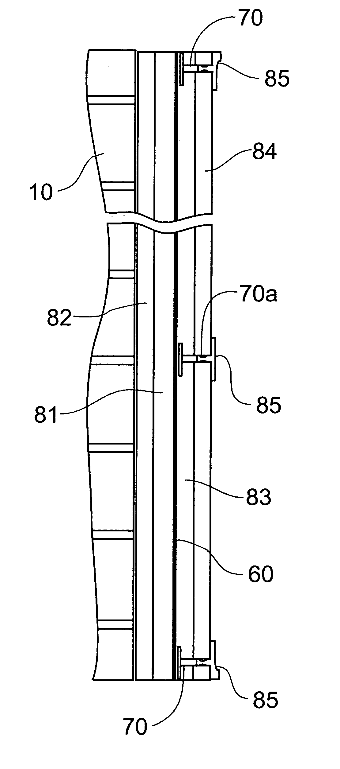
[0063] Five separate experimental insulation systems are constructed in Columbus, Ohio, each experimental system having R-13 insulation placed a concrete block wall with a vapor retarder placed on or within the insulation at a chosen location. Each of the five experimental insulation systems are discussed in detail below and are shown schematically in FIGS. 8a, 9a, 10a, 11a, and 12a. The interior of the building for each of the experimental systems has a temperature of 65° F. and a relative humidity of 40%.

[0064] The outside temperature and the outside dew point temperature on both Jan. 1, 2002 and Aug. 1, 2002 are obtained, such as from hourly climatic data, and the temperature of the vapor retarders in each of the experimental systems are calculated. Graphs for the data for each of the five experimental systems are depicted in FIGS. 8b-8c, 9b-9c, 10b-10c, 11b-11c, a...


PUM


Abstract

A method for positioning a vapor retarder within an insulation system to reduce condensation within the insulation system is provided. The incremental change in temperature per R-value of insulation is calculated by determining the temperature differential between the exterior temperature and the interior temperature and dividing this temperature differential by the R-value of insulation. Various possible temperatures for the vapor retarder within the insulation may be determined using the incremental change in temperature. The R-values of the insulation layers on either side of the vapor retarder may be determined by a condensation potential analysis. Preferably, the vapor retarder is positioned within the insulation system at a location where its temperature remains above the interior dew point temperature in the summer and above the exterior dew point temperature in the winter. An insulation system including a variably positioned vapor retarder is also provided.

Description

TECHNICAL FIELD AND INDUSTRIAL APPLICABILITY OF THE INVENTION [0001] The present invention relates generally to an insulation system that contains a vapor retarder and more particularly to an insulation system in which the vapor retarder is variably positioned between insulative layers depending on geographic location and / or condensation potential. BACKGROUND OF THE INVENTION [0002] Fiber insulation is typically formed of mineral fibers (e.g., glass fibers) or organic fibers (e.g., polypropylene fibers), bound together by a binder material. The binder material gives the insulation product resiliency for recovery after packaging and provides stiffness and handleability so that the insulation product can be handled and applied as needed in insulation cavities of buildings. During manufacturing, the fiber insulation is cut into lengths to form individual insulation products, and the insulation products are packaged for shipping to customer locations. One typical insulation product is a...

Claims


Application Information

Patent Timeline
IPC IPC(8): E04B1/76E04B2/00E04B5/00E04B9/00
CPCE04B1/76
Inventor HETTLER, NEIL R.SMITH, MARK H.WEIR, CHARLES R.CLIPPINGER, BRET A.
Owner OWENS CORNING INTELLECTUAL CAPITAL LLC
Learn More