
Apparatus and method for multihop MPLS/IP/ATM/frame relay/ethernet pseudo-wire

a multi-hop, pseudo-wire technology, applied in the direction of data switching by path configuration, digital transmission, data switching networks, etc., to achieve the effect of facilitating the inter-working of layer-2 tunnelling protocol, eliminating end to end signalling, and eliminating end to end encapsulation negotiation

Inactive Publication Date: 2005-07-07
RPX CLEARINGHOUSE
View PDF11 Cites 95 Cited by
  • Summary
  • Abstract
  • Description
  • Claims
  • Application Information

AI Technical Summary

Benefits of technology

[0016] An advantage of the present invention is that it eliminates end to end signalling between the multihop pseudo-wire provider edge devices. In other words, label distribution protocol downstream unsolicited (LDP-DU) is eliminated.
[0017] Another advantage of the present invention is that it eliminates end to end encapsulation negotiation.
[0018] Yet another advantage of the present invention is the facilitation of inter-working between BGP / LDP layer-2 VPN signalling protocols. It also facilitates the inter-working of layer-2 tunnelling protocol (L2TP) and MPLS-based pseudo-wire.

Problems solved by technology

Since LANE operates in layer-2, it is limited to creating bridge networks (and not routed networks) over the ATM switching fabric.

Method used


Image

  • Apparatus and method for multihop MPLS/IP/ATM/frame relay/ethernet pseudo-wire
  • Apparatus and method for multihop MPLS/IP/ATM/frame relay/ethernet pseudo-wire
  • Apparatus and method for multihop MPLS/IP/ATM/frame relay/ethernet pseudo-wire

Examples


Embodiment Construction

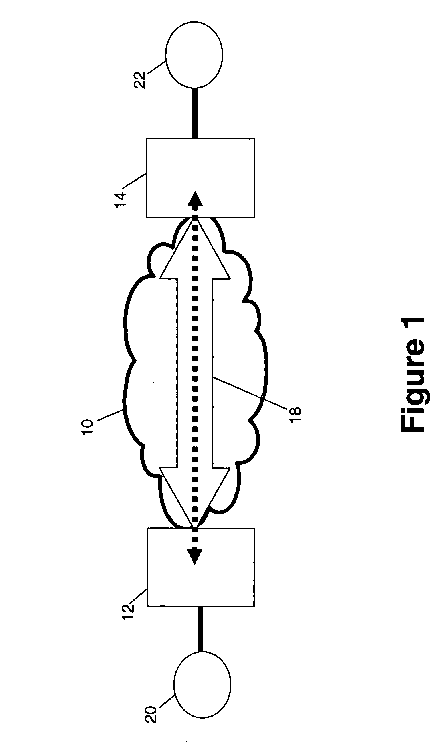
[0029] Referring to FIG. 1, there is illustrated an MPLS or IP network 10 extending between provider edge devices 12 and 14. If the network 10 is an MPLS network, the devices 12 and 14 are preferably MPLS enabled routers.

[0030] An MPLS network typically includes a label edge router (LER), a label switch path (LSP) and a label switch router (LSR). LERs are routers on the edge of the network that attach labels to packets based on a forwarding equivalence class (FEC), while LSRs are routers capable of forwarding packets according to a label switching algorithm. Thus, the devices 12 and 14 are LERs when the network 10 is an MPLS network. Once packets have been assigned a label by the LER, they are forwarded along the LSP. An LSP is essentially the predetermined route that a set of packets bound to an FEC traverse through an MPLS network to reach their destination. As packets are forwarded along the LSP, each LSR makes forwarding decisions based solely on the contents of the label. At e...


PUM


Abstract

An apparatus for emulating a layer-2 service over at least one network is disclosed. The apparatus includes a signal transmission path. Two provider edge devices are located at opposite ends of the signal transmission path. A provider device is located along the signal transmission path, and this provider device divides the signal transmission path into segments. One of the provider edge devices includes code for adding a demultiplexing header onto data units prior to the data units being transmitted along the signal transmission path.

Description

FIELD OF THE INVENTION [0001] This invention relates to emulating services over networks and, in particular, multihop MPLS / IP / ATM / frame relay pseudo-wire for emulating services. BACKGROUND OF THE INVENTION [0002] The word emulation has special meaning in the fields of computers and telecommunications. Emulation occurs when the function of a device, program, etc. is imitated by modifications to hardware or software that allow the imitating device, system etc. to accept the same data, execute the same programs, and / or achieve the same results as what is being imitated. [0003] Emulation can have significance in the context of geographically spaced apart customer networks. For example, these customer networks could be running native layer-2 services. (A native service is to be contrasted to an emulated service, in that where the native service is being provided, the service is not being imitated.) These customer networks could be connected together by a multi-protocol label switching (M...

Claims


Application Information

Patent Timeline
IPC IPC(8): H04L12/28H04L12/46H04L12/56H04L29/06
CPCH04L12/4608H04L63/164H04L45/50H04L12/4633
Inventor OULD-BRAHIM, HAMID
Owner RPX CLEARINGHOUSE
Learn More