
Protective sheath for drug coated stent

a technology of protective sheath and drug coating, which is applied in the field of protective sheath of biomedical stents, can solve the problems of insufficient protection of the stent, and achieve the effect of preventing friction

Inactive Publication Date: 2005-06-30
MEDTRONIC VASCULAR INC
View PDF13 Cites 83 Cited by
  • Summary
  • Abstract
  • Description
  • Claims
  • Application Information

AI Technical Summary

Benefits of technology

[0008] It is an object of this invention to provide a sheath to be used in a packaging system to prevent friction on a drug coated stent from removing the drug applied on the stent by overcoming the deficiencies and limitations described above.
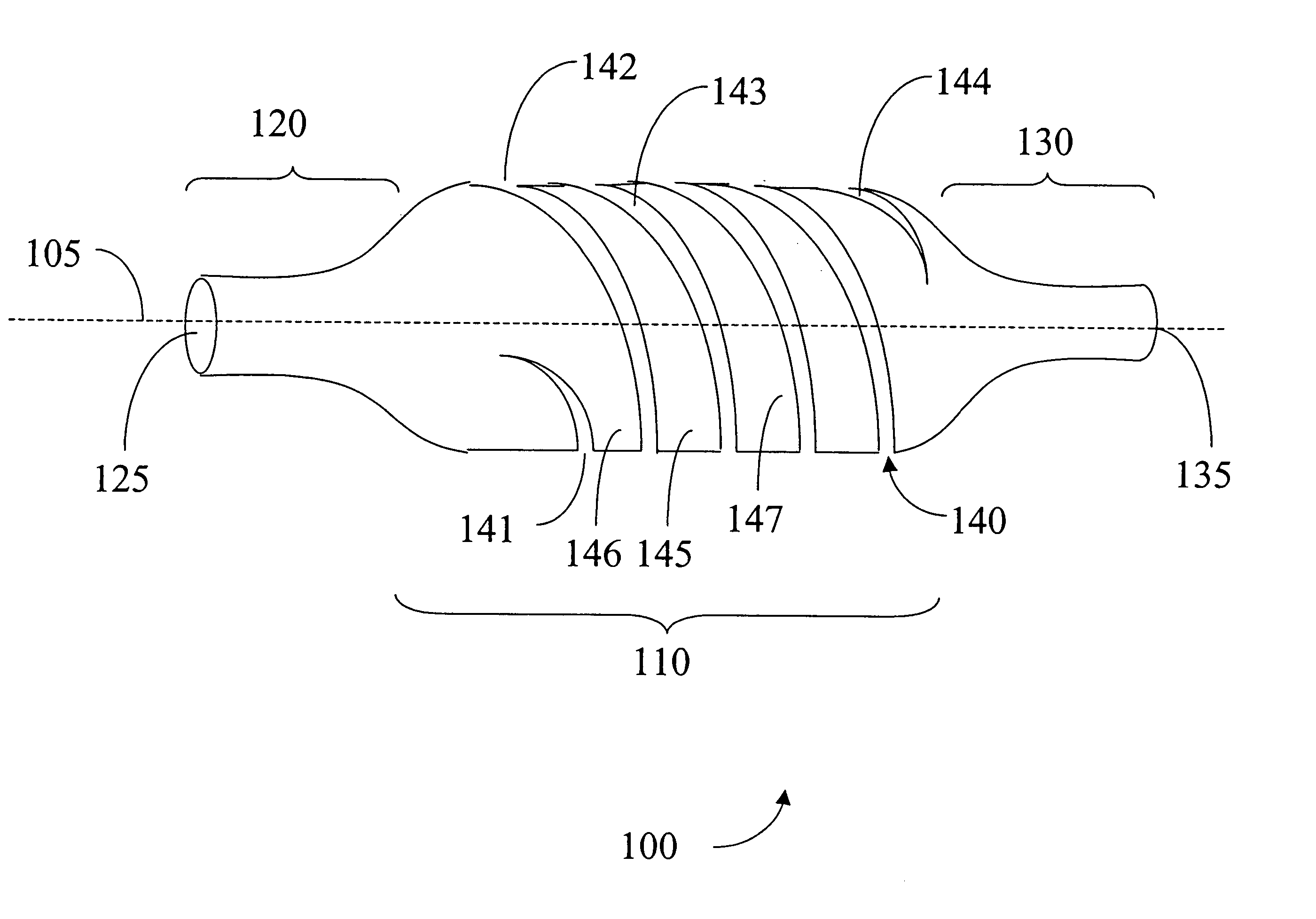
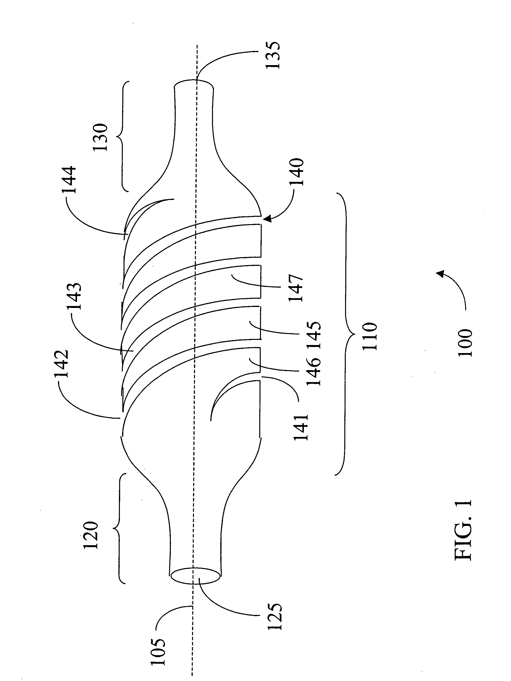
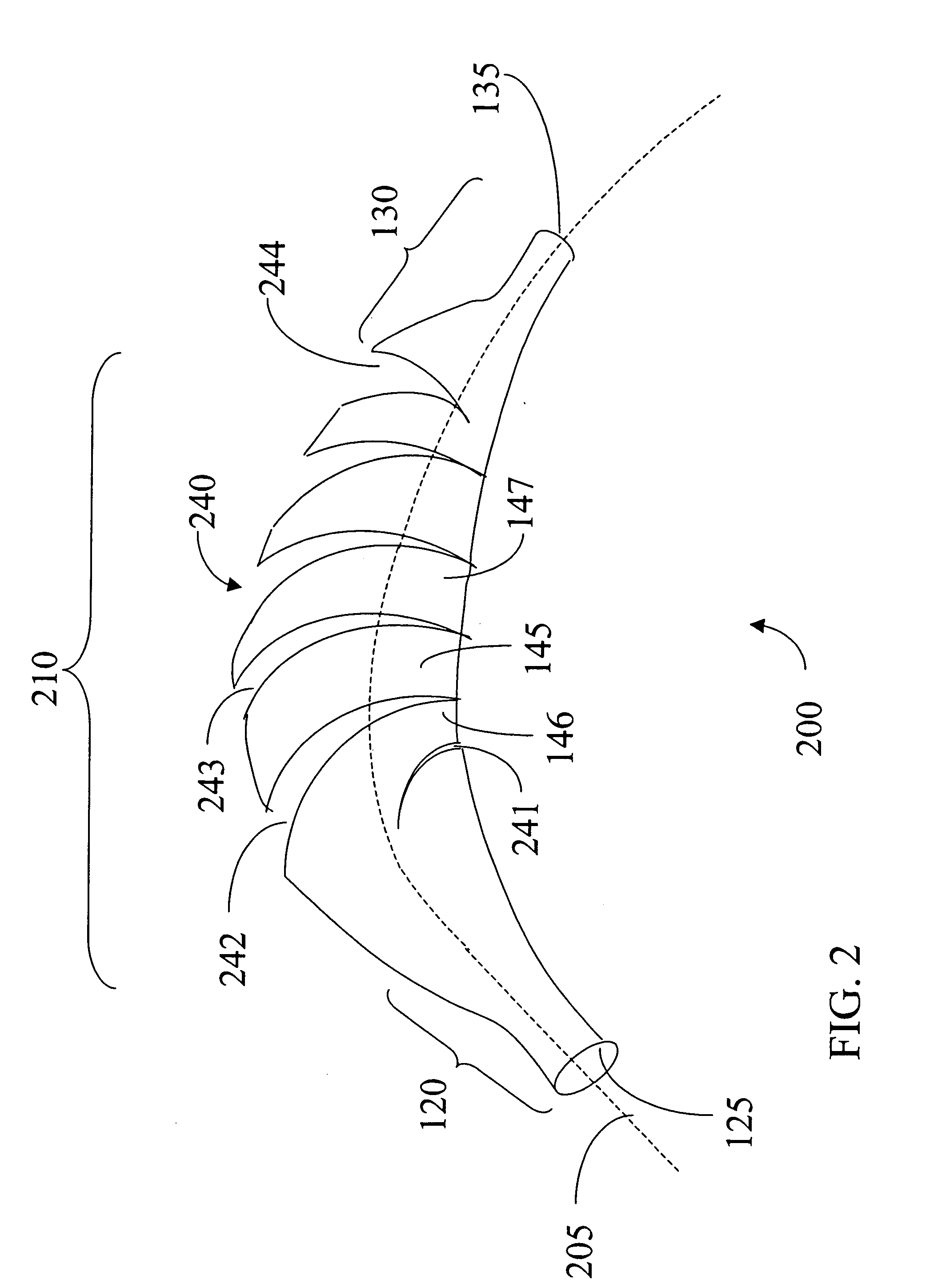
[0009] One aspect of the present invention provides a system for packaging a drug coated stent, including a transport package body with an arcuate catheter guide. The system also includes a catheter attached to the drug coated stent and received in the catheter guide. A sheath is disposed on the catheter and encloses the drug coated stent. The sheath includes at least one reduced thickness region to increase flexibility of the sheath.
[0010] A second aspect of the present invention provides a sheath for protecting a drug coated stent, including a body portion including a central lumen for receiving a drug coated stent. The body portion includes at least one reduced thickness region to increase flexibility of the sheath.

Problems solved by technology

However, if the drug coated stents are packaged to ship to a medical practitioner, without a protective sheath, some of the drug on the stent may rub off of the stent while it is in the package.
In all these packaging systems the protective sleeve is not always sufficient to prevent a quantity of drug from being rubbed off the stent.

Method used


Image

  • Protective sheath for drug coated stent
  • Protective sheath for drug coated stent
  • Protective sheath for drug coated stent

Examples


second embodiment

[0038]FIG. 8, in which like elements share like reference numbers with FIG. 1, shows a sheath 400. Several circumferential cuts including 442, 443, 446, 447 provide the flexibility to sheath 400. The circumferential cut 446 is in between circumferential cuts 442 and 443 and on the opposite side of the main body portion 110 of the sheath 400. Main body section 445 is between circumferential cuts 442 and 443. The circumferential cuts including 442, 443, 446, 447 may extend the length of the main body portion 110. The spacing between cuts 442, 443, 446, 447 and the length and width of cuts 442, 443, 446, 447 may vary according the dimensions of the sheath 400.

third embodiment

[0039]FIG. 9, in which like elements share like reference numbers with FIG. 1, shows a sheath 500. Several circumferential cuts including 542, 543, 546, 547 and 548 provide the flexibility to sheath 500. The circumferential cut 542 is directly opposed to circumferential cut 546, which is on the opposite side of the main body portion 110 of the sheath 500. The circumferential cut 543 is directly opposed to circumferential cut 547, which is on the opposite side of the main body portion 110 of the sheath 500. Main body section 545 is between circumferential cuts 542 and 543. Circumferential cut 548 is disposed between the opposing pairs of cuts 542, 546, 545 and 547 and within a portion of the body section 545. The center of the arc of the cut 548 is about right angle with the center of the arc of the cuts 542, 543, 546 and 547. A cut directly opposing cut 548 and about the same length as cut 548 is on the back side of the main body portion 110. The circumferential cuts including 542, ...

fourth embodiment

[0041]FIG. 10, in which like elements share like reference numbers with FIG. 1, shows a sheath 600. Several staggered cuts including 642, 643 and 644 provide the flexibility to sheath 600. Each cut on sheath 600 comprises two circumferential cut sections 650 offset and connected by an axial cut section 660. Thus at least a portion of cut regions including 642, 643 and 644 are along at least a portion of a circumference of a main body portion 110 of the sheath 100. Axial cut section 660 is parallel the central axis 105 of the main body portion 110 of the sheath 100.

[0042] The cuts 642, 643 and 644 are located in a staggered relation to each other. For example, cut 643 is over and down from 642 while cut 644 is over and down from cut 643 and so forth. All the cuts including 642, 643 and 644 form a spiral pattern around the main body portion 110.

[0043] The cuts including 642, 643 and 644 may extend the length of the main body portion 110. The spacing between cuts 642, 643 and 644 and ...


PUM


Abstract

The present invention provides a system for packaging a drug coated stent, including a transport package body including an arcuate catheter guide and a catheter. The catheter has a drug coated stent disposed thereon to be received in the catheter guide. A sheath including at least one reduced thickness region therein to increase flexibility of the sheath is disposed on the catheter, which encloses the drug coated stent.

Description

RELATED APPLICATIONS [0001] This application claims the benefit of U.S. Provisional Patent Application 60 / 532,797 filed Dec. 24, 2003.FIELD OF THE INVENTION [0002] This invention relates generally to protective sheaths for biomedical stents. More specifically, the invention relates to a protective sheath for biomedical drug coated stents to be used in packaging for shipping. BACKGROUND OF THE INVENTION [0003] Drug coated stents can improve the overall effectiveness of angioplasty and stenotic procedures performed on the cardiovascular system and other vessels within the body by delivering potent therapeutic compounds at the point of infarction. Drugs such as anti-inflammatants and anti-thrombogenics may be dispersed within the drug-polymer coating and released after insertion and deployment of the stent. These drugs and coatings can reduce the trauma to the local tissue bed, aid in the healing process, and significantly reduce the narrowing or constriction of the blood vessel that c...

Claims


Application Information

Patent Timeline
IPC IPC(8): A61F2/00A61F2/06
CPCA61F2002/9583A61F2/0095
Inventor WATSON, JAMES R.DOTY, DAVID
Owner MEDTRONIC VASCULAR INC
Learn More