Image forming device
- Summary
- Abstract
- Description
- Claims
- Application Information
AI Technical Summary
Benefits of technology
Problems solved by technology
Method used
Image
Examples
first embodiment
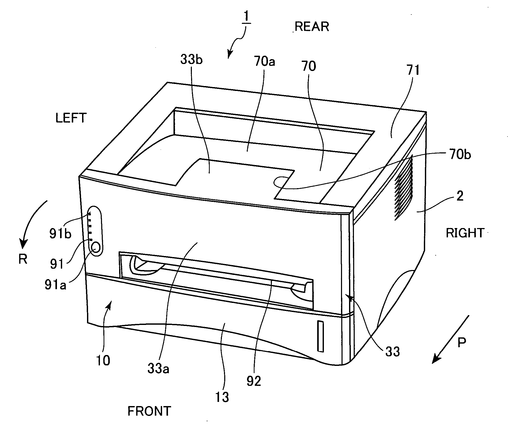
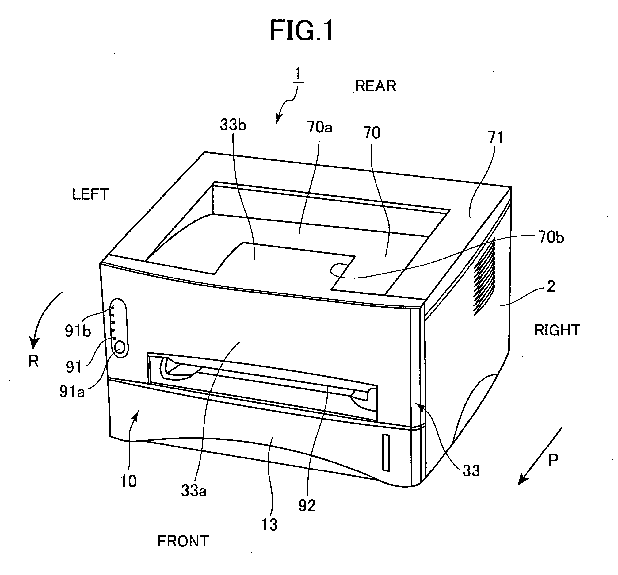
[0028] Next, the present invention will be described with reference to FIGS. 1 to 7 in which the image-forming device according to the present invention is applied to a laser beam printer.
[0029] As shown in FIG. 1, a laser beam printer 1 according to the first embodiment includes a main casing 2 having a substantially rectangular parallelepiped shape. A sheet supply cassette 10 for supporting a stack of recording sheets S (FIG. 6) is disposed in the lower section of the main casing 2. The sheet supply cassette 10 is formed with a grip 13 and can be detached from the main casing 2 by being pulled toward the front as indicated by an arrow P.
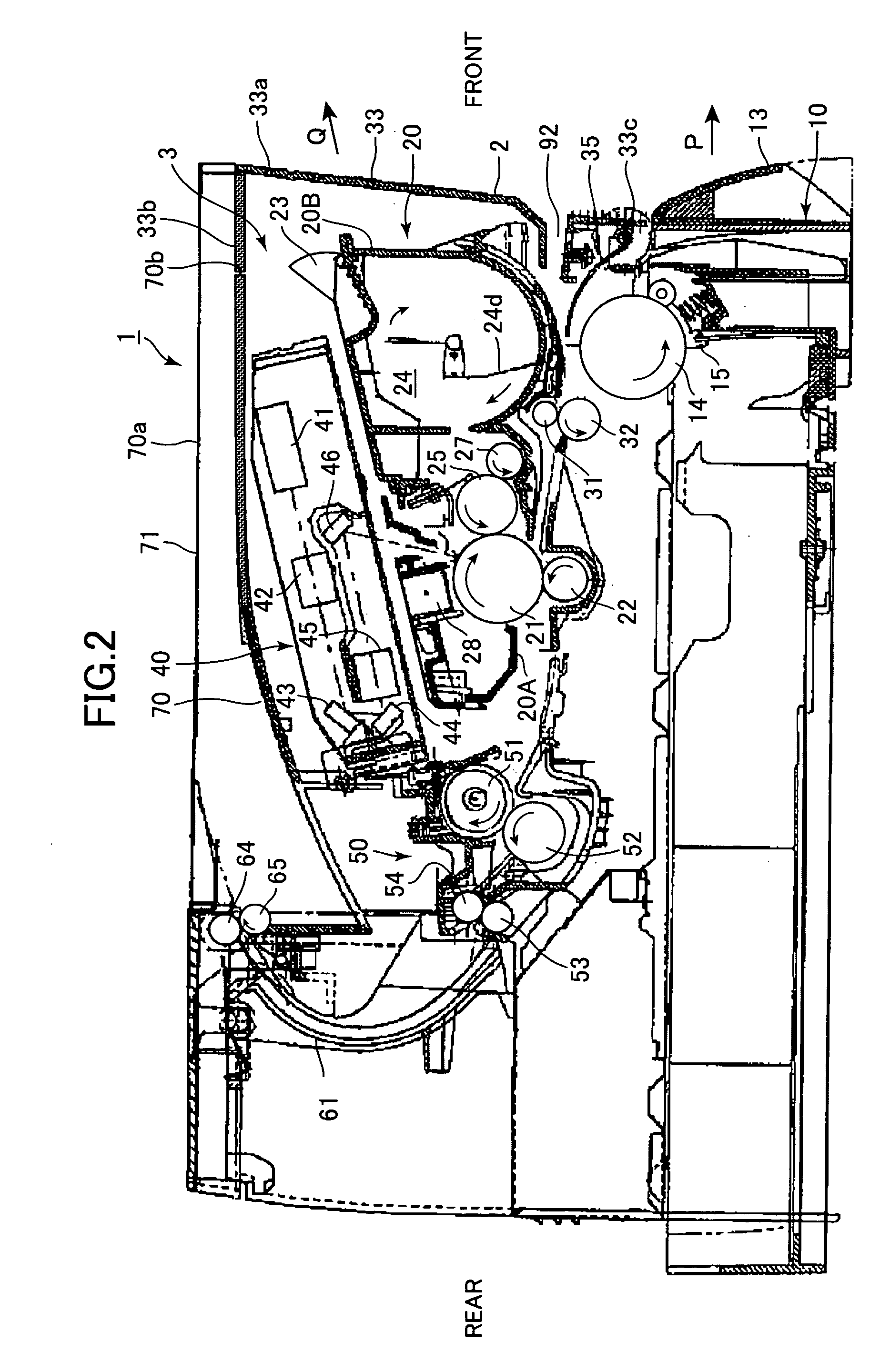
[0030] Although not shown in the drawings, the sheet supply cassette 10 includes a pressing plate for mounting a stack of recording sheets S and a spring for urging the pressing plate upward. As shown in FIG. 2, a sheet supply roller 14 is disposed inside the main casing 2 so as to be rotatable in a direction indicated by an arrow. An uppermost sh...
third embodiment
[0060] Next, a laser beam printer 200 according to the present invention will be described with reference to FIGS. 10 and 11. Note that components similar to that of the above-described embodiments will the assigned with the same numberings, and description thereof will be omitted to avoid duplication in explanation.
[0061] As shown in FIG. 11, the laser beam printer 200 has a cover 233 disposed on the front surface of the main casing 2 that differs from the cover 33 according to the first embodiment. The cover 233 includes a front cover part 233a and a top cover part 233b configured to pivot about an axis C2 on the front cover part 233a. A step part 33e is formed in the top cover part 233b. An angle formed by the front cover part 233a and the top cover part 233b is maintained slightly smaller than 90° (such as 80°) by a spring member 33d.
[0062] The laser beam printer 200 also has a discharge tray 270. As shown in FIG. 10, the discharge tray 270 includes a tapered part 276 formed on...
fourth embodiment
[0064] Next, a laser beam printer 300 according to the present invention will be described with reference to FIG. 12. Description of components similar to that of the above-described embodiments will be omitted to avoid duplication in explanation.
[0065] The laser beam printer 300 shown in FIG. 12 includes a main casing 302 and a sheet supply cassette 310 that is inserted into the front side of the main casing 302. The main casing 302 is formed with an opening 334 continuous with the cutout part 70b. The sheet supply cassette 310 includes a front wall 311 that constitutes the entire front surface of the main casing 302 and extends to the top surface of the main casing 302. The front wall 311 includes a front cover part 311a and a plate-shaped top cover part 311b that are integrally formed and function as a cover for the opening 334 and the cutout part 70b. The front wall 311 moves forward and rearward during operations to open and close the sheet supply cassette 310, thereby exposing...
PUM
 Abstract
Description
Claims
Application Information
 - R&D
- Intellectual Property
- Life Sciences
- Materials
- Tech Scout
- Unparalleled Data Quality
- Higher Quality Content
- 60% Fewer Hallucinations
Browse by: Latest US Patents, China's latest patents, Technical Efficacy Thesaurus, Application Domain, Technology Topic, Popular Technical Reports.
© 2025 PatSnap. All rights reserved.Legal|Privacy policy|Modern Slavery Act Transparency Statement|Sitemap|About US| Contact US: help@patsnap.com


