
Method for patching element defects by ink-jet printing

a technology of inkjet printing and defects, applied in printing, printing mechanisms, other printing apparatuses, etc., can solve the problems of inhomogeneous film, phase separation during film drying, yield and quality of element production, etc., and achieve the effect of saving tim

Inactive Publication Date: 2005-06-30
IND TECH RES INST
View PDF9 Cites 14 Cited by
  • Summary
  • Abstract
  • Description
  • Claims
  • Application Information

AI Technical Summary

Benefits of technology

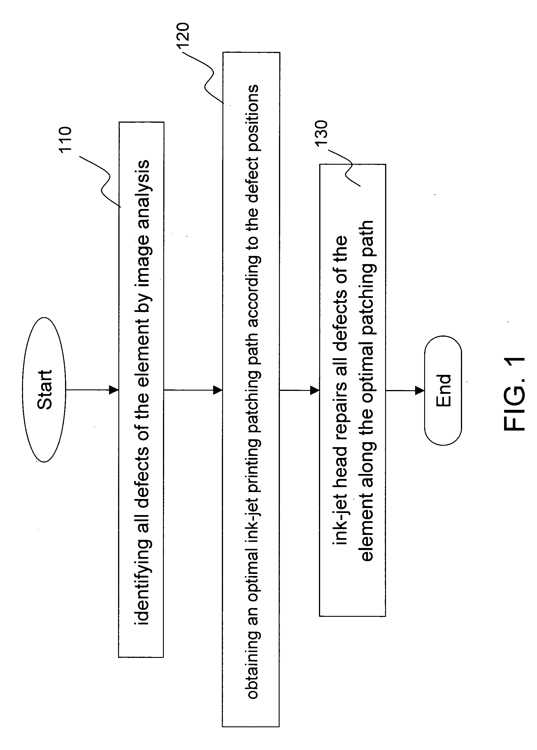
[0008] The object of the invention is to provide a method for patching defects of an element by ink-jet printing. The method first detects all defect points; calculating an optimal patching path; then patching with ink-jet printing according to the optimal path.
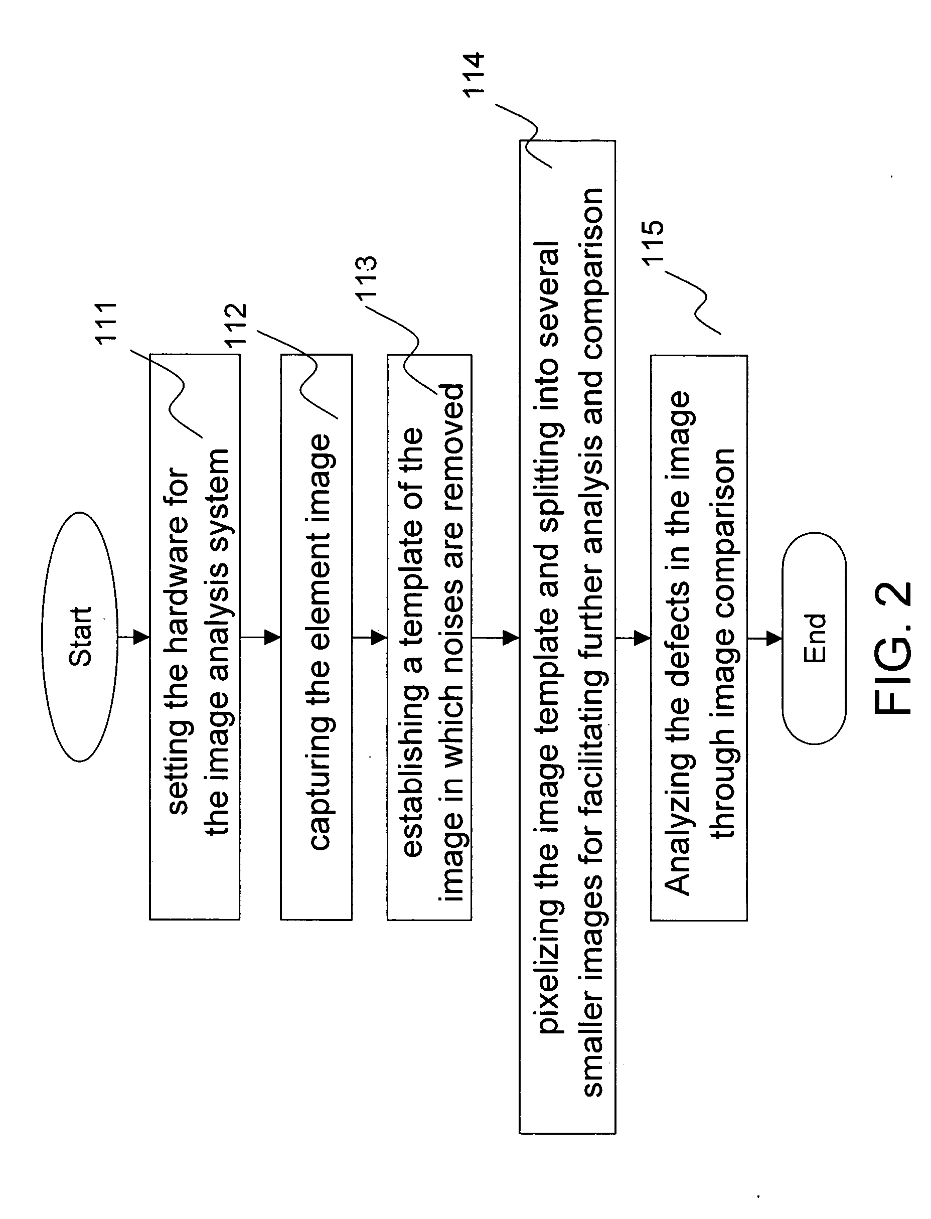
[0009] A method for patching element defects by ink-jet printing according to the invention applies an optimal patching path so that the ink-jet head travels with a shortest distance that also saves time and prevents the nozzles of the ink-jet head from being clogged since a longer waiting of non-ejection. The method includes steps of identifying all defects of the element and obtaining the optimal ink-jet printing path of the ink-jet head. The ink-jet head repairs all defects of the element at a shortest distance along the optimal patching path. Any a larger or wider defect that requires several times of ejection and movement of the ink-jet head is identified as a plurality of defect positions. The step of identifying the defect positions is processed through image analysis.
[0010] The process of calculating an optimal (shortest) ink-jet printing patching path according to the defect positions includes the following steps. Establishing a plurality of defect coordinates (Xi,Yi), i=1 to n; referring on a reference coordinate (X0,Y0) of the nozzle of the ink-jet head, and calculating the distances Ri between the reference point and the plurality of defect positions, Ri=((Xi−X0)2+(Yi−Y0)2)1 / 2; selecting a defect position with a minimal Ri value as the next patching position. The aforesaid steps are repeated to get the further next patching position when the ink-jet head moves and patches a patching position. Another manner is to find out the order of all the patching positions. When a defect position is selected, the patching position is set as the ink-jet head position for calculating the relative distances and selecting a next patching position, the steps are repeated till all the positions are arranged as an optimal patching path.

Problems solved by technology

Therefore, the inhomogeneous film is a major problem of ink-jet printing process.
The secondary problem is the phase separation during the film drying.
The aforesaid problems influence the yield and quality of the element production.
Especially, the ink-jet printing process is hard to improve the resolution for high precision elements.
Therefore, there are defect holes formed.
For example, a hole on a polymer light emitter diode causes current leakage.
The defects greatly influence the elements.
Other problems, such as substrate contamination, deconcentrated ink droplets and clogged ink-jet head, etc., also cause printing defects.

Method used


Image

  • Method for patching element defects by ink-jet printing
  • Method for patching element defects by ink-jet printing
  • Method for patching element defects by ink-jet printing

Examples


Embodiment Construction

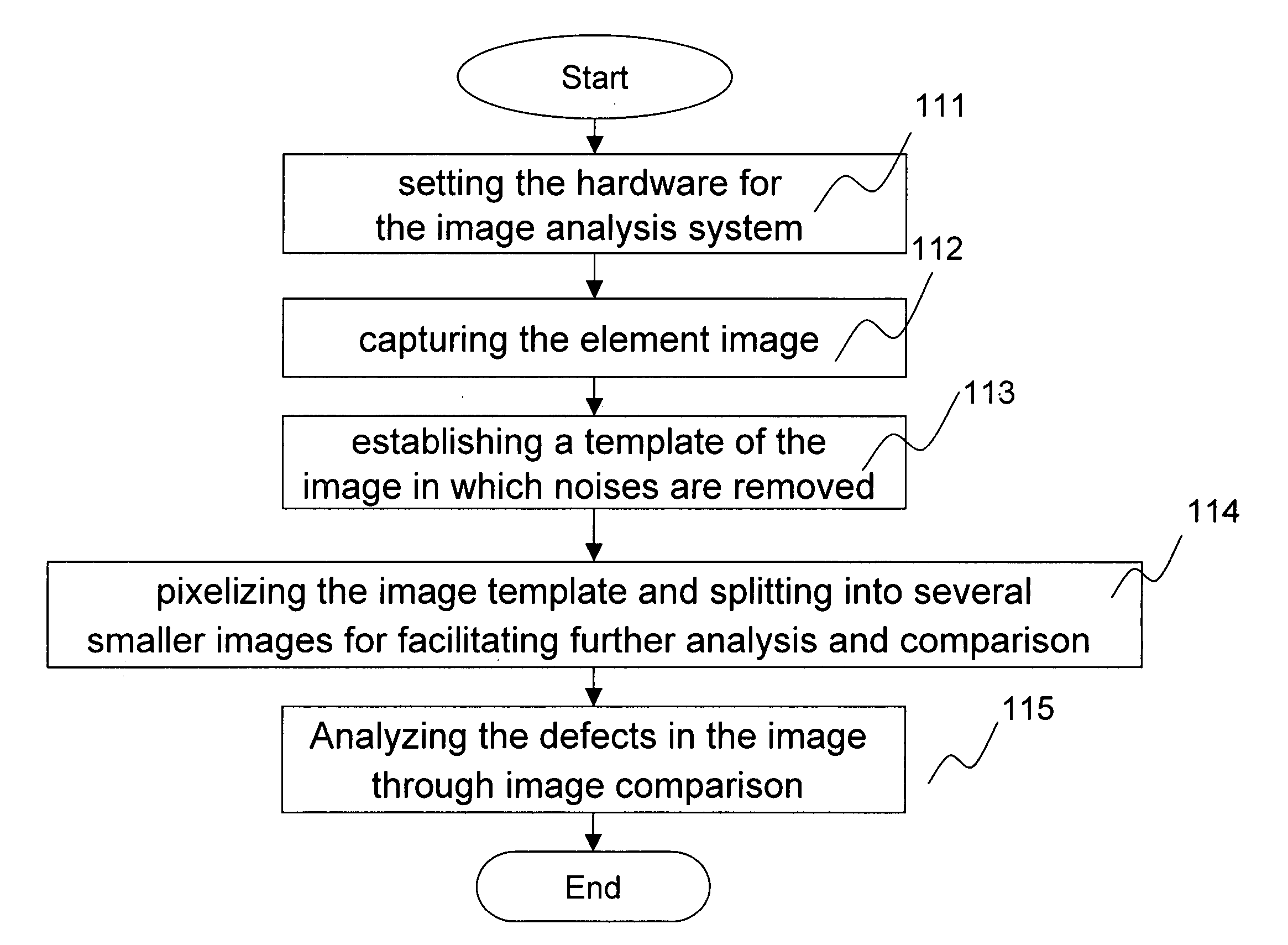
[0017] The invention provides a method for patching element defects by ink-jet printing. Defects usually take place in ink-jet printing processes include: (1). the lattice structure of element breaking to lead to overflow and ink mixed, (2). substrates are contaminated to lead to attach particle, (3). ink-jet printing generated satellite drops, (4). nozzles of print head was clogged, (5). ink-jet printing unstable, (6). the surface is not well treated, the hydrophilic and hydrophobic property of the surface different to lead fluid separation, (7). the polar characteristic of ink repels with bank. The disclosed patching process is mainly for repairing the defects of No. 4˜No. 7, mainly in the under-filled problem. The method includes steps of identifying all defects of the element by image analysis and obtaining an optimal ink-jet printing path of the ink-jet head. The ink-jet head repairs all defects of the element at a shortest distance along the optimal patching path. The detectio...


PUM


Abstract

A method for patching element defects by ink-jet printing includes steps of identifying all defects of the element by image analysis and obtaining an optimal ink-jet printing path of the ink-jet head. The ink-jet head repairs all defects of the element with the shortest distance along the optimal patching path. Moreover, the ink-jet head repairs all defects of the element in a stable manner so as to increase the yield rate.

Description

BACKGROUND OF THE INVENTION [0001] 1. Field of the Invention [0002] The invention generally relates to method for patching defects of an element, and in particular relates to a method for patching defects of an element by ink-jet printing. [0003] 2. Related Art [0004] Ink-jet printing is a delicate, high-repetitive process being applied in the electronic industry of precision elements for achieving the manufacturing requirements and trend of automated, minimized, low-cost, less process and less environmental impact. It is applicable to the printings of precision elements of different materials. However, the ink-jet printing applied on high-resolution film elements, such as micro lenses array and polymer light emitter diodes (PLED), requires highly precise positioning for ejecting ink droplets on predetermined positions. Moreover, the solvent (water or other organic solvent) in the ink droplets adhered to the substrate has to vaporize before the film forms. But the uniformity of the ...

Claims


Application Information

Patent Timeline
Patent Type & Authority Applications(United States)
IPC IPC(8): B41J2/165B41J2/21H10K99/00
CPCH01L51/0005B41J2/2139H10K71/135
Inventor CHENG, KEVINLIN, CHIH-JIANCHIU, WAN-WENLU, JHIH-PINGCHENG, FU-KANGCHANG, JANE
Owner IND TECH RES INST
Learn More