
Power supply apparatus

a power supply and battery technology, applied in the direction of secondary cell servicing/maintenance, transportation and packaging, and battery arrangement for several simultaneous batteries, can solve the problems of inability to safely change all of battery packs, inability to safely charge batteries, etc., to prevent thermal breakdown of discharge current interruption, safe charge battery packs, and effective prevent the effect of fet breakdown

Inactive Publication Date: 2005-06-30
SANYO ELECTRIC CO LTD
View PDF5 Cites 15 Cited by
  • Summary
  • Abstract
  • Description
  • Claims
  • Application Information

AI Technical Summary

Benefits of technology

[0010] When charging the battery pack in which the discharge current interruption FET is in OFF state, the device disclosed in this Document turns the discharge current interruption FET from OFF state to ON state and charges it in the quick charge mode. Since a current is applied to the battery pack charged in the quick charge mode in this state not through the parasitic diode but the discharge current interruption FET in ON state, heat generation by the parasitic diode can be eliminated. The reason is that, in the discharge current interruption FET in ON state connected to the parasitic diode in parallel, voltage drop is very small as compared with the parasitic diode. This can reduce power consumption.
[0012] The present invention has been developed for solving the disadvantage. It is an important object to provide a power supply apparatus having a battery pack and a charge circuit capable of safely charging a battery pack containing an abnormal battery or a battery whose battery voltage is low as compared with other battery, and of effectively preventing breakdown of FET due to heat generation of parasitic diode.
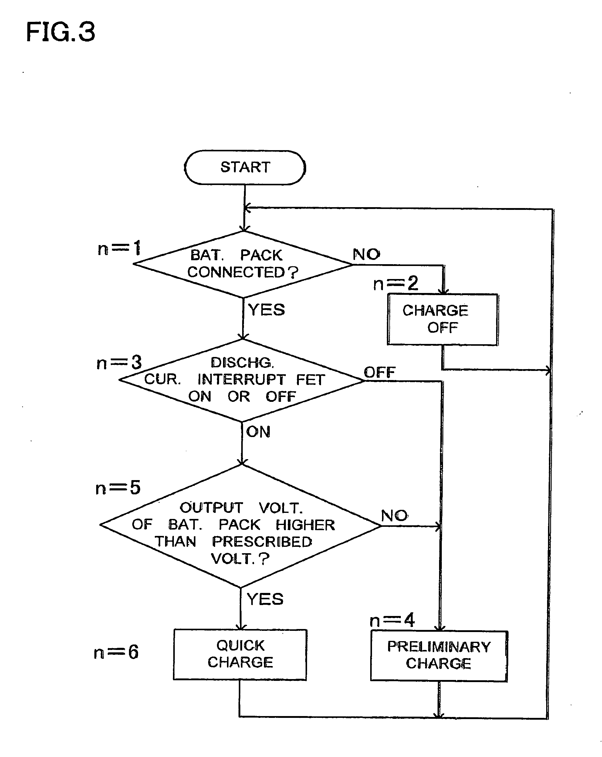
[0015] The aforementioned power supply apparatus has a feature that can safely charge a battery pack containing an abnormal battery or a battery whose battery voltage is low as compared with other battery, and can effectively prevent breakdown of FET due to heat generation of parasitic diode. The reason is that the charge current switching portion of the charge circuit detects the output voltage of the battery pack, and switches the charge current so as to change the battery pack in the main charge mode when the output voltage is higher than the prescribed voltage and to charge the battery pack in the preliminary charge mode with a current smaller than that in the main charge mode when the output voltage is lower than the prescribed voltage, and the charge current switching portion charges the battery pack in the preliminary charge mode in the state where the voltage of any battery in, the battery pack becomes lower than the minimum voltage, even if in the state where the output voltage, of the battery pack is higher than the prescribed voltage, in the aforementioned power supply apparatus. The power supply apparatus of this structure charges the battery pack not in the main charge mode but in the preliminary charge mode with a current smaller than that in the main charge mode in the state where the voltage of any battery becomes lower than the minimum voltage, in other words, in the state where the discharge current interruption FET is in OFF state, even if the output voltage of the battery pack is higher than the prescribed voltage. Accordingly, it is prevented that a large charge current flows through the discharge current interruption FET in OFF state. Thus, it is possible to effectively prevent thermal breakdown of the discharge current interruption FET in the main charge mode.
[0016] Furthermore, when the discharge current interruption FET is in OFF state, the aforementioned power supply apparatus does not switch the discharge current interruption FET from OFF state to ON state to charge the battery pack with a large charge current in the main charge mode similarly to a conventional battery pack, but charges the battery pack with a current smaller than that in the main charge mode in the preliminary charge mode. Accordingly, it is possible to charge a battery pack in which the voltage of any battery becomes lower than the minimum voltage after it is confirmed that the voltages of all batteries become higher than the minimum voltage, in other words, after it is confirmed that the battery pack is not abnormal, by initially charging the battery pack with a small current in the preliminary charge mode. Therefore, the aforementioned power supply apparatus has a feature that can safely charge a battery pack without initially charging a battery pack containing an abnormal battery with a large current.

Problems solved by technology

However, this device forcedly turns the discharge current interruption FET in OFF state to ON state, and charges the battery pack with a large current in the quick charge mode.
Accordingly, although the device can prevent heat generation of FET, it cannot safely change all of battery packs.
On the contrary, since the device, which forcedly turns the discharge current interruption FET from OFF sate to ON state to charge a battery pack in the quick charge mode, charges even a battery pack containing an abnormal battery, it has a disadvantage that cannot safely charges a battery pack.

Method used


Image

  • Power supply apparatus
  • Power supply apparatus
  • Power supply apparatus

Examples


Embodiment Construction

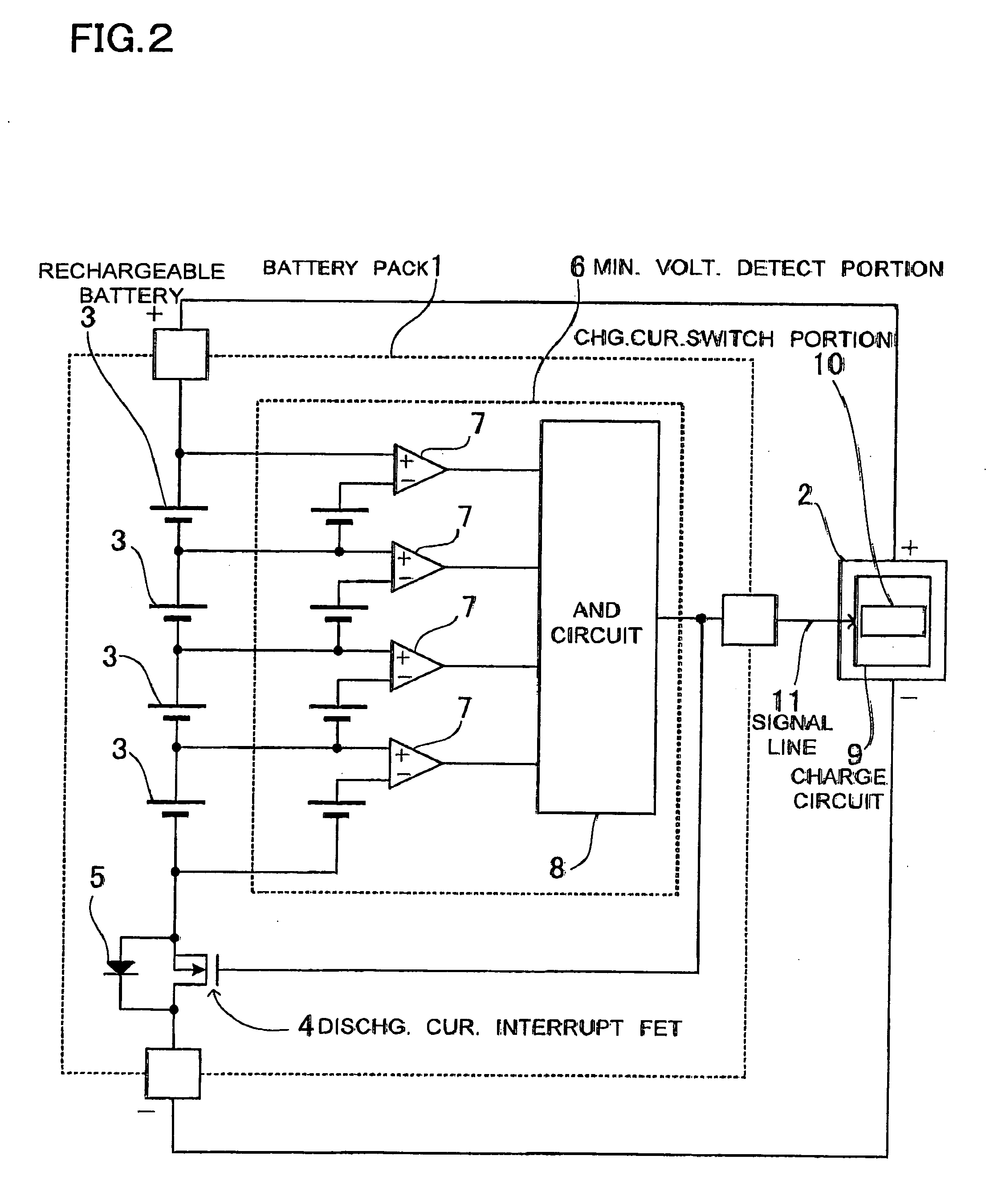
[0020] A power supply apparatus shown in FIG. 2 has a battery pack 1 and a charger 2 which charges the battery pack 1. The battery pack 1 includes a discharge current interruption FET 4 which is connected to the rechargeable batteries 3 in series and cuts off the discharge current, and a minimum voltage detecting portion 6 which compares each battery voltage with a minimum voltage, and switches the discharge current interruption FET 4 from ON state to OFF state to cut off the discharge current when the voltage of any battery becomes lower than the minimum, voltage, as an overdischarge detection portion. The battery pack 1 is detached from the charger 2, and is used as a power supply for electrical equipment (not shown) which is separately prepared,.

[0021] The rechargeable batteries 3 are lithium-ion batteries connected to each other in series. In the battery pack 1 of the figure, four lithium-ion batteries are conned in series. In the battery pack 1, its output voltage increases as...


PUM


Abstract

A battery pack includes a discharge current interruption FET which cuts off the discharge current, and a minimum voltage detecting portion which switches the discharge current interruption FET from ON to OFF state when the voltage of any battery becomes lower than a minimum voltage. The charge circuit includes a charge current switching portion which switches the charge current so as to charge the battery pack in a main charge mode when the output voltage is higher than a prescribed voltage, and in a preliminary charge mode with a small current when the output voltage is lower than the prescribed voltage. The charge current switching portion charges the battery pack in the preliminary charge mode in the state where the OFF signal of the discharge current interruption FET is provided, even in the state where the output voltage of the battery pack is higher than the prescribed voltage.

Description

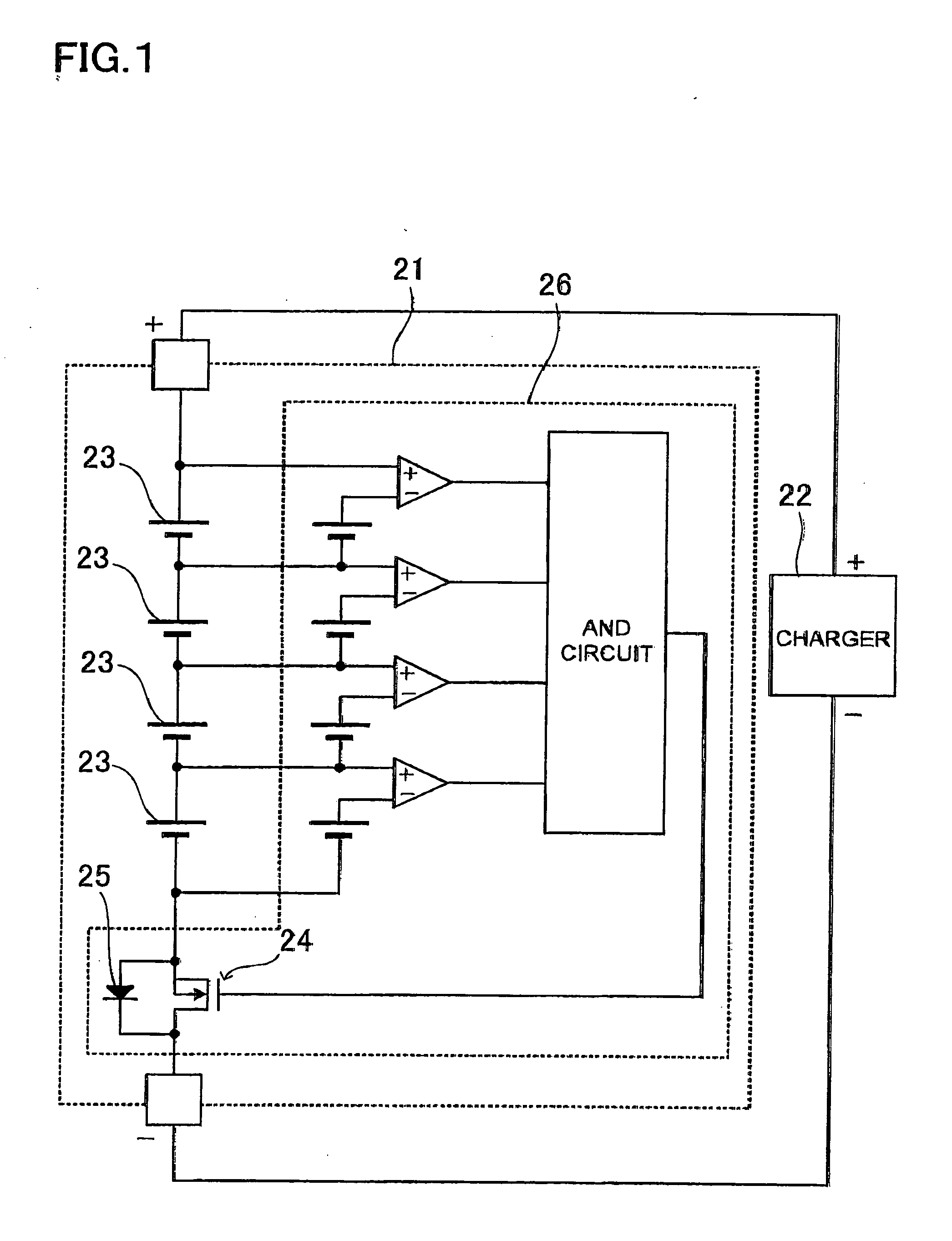
BACKGROUND OF THE INVENTION [0001] 1. Technical Field [0002] The present invention relates to a power supply apparatus having a battery pack with a plurality of rechargeable batteries connected in series, and a charge circuit which charges the battery pack. [0003] 2. Description of Related Art [0004]FIG. 1 shows a circuit diagram of a battery pack 21 having a plurality of batteries 23; connected in series. The battery pack 21 has an overdischarge protection circuit 26 which prevents overdischarge of each battery 23. The overdischarge protection circuit 26 detects the voltage of each battery 23. When the voltage of any battery 23 becomes lower than a minimum voltage, the overdischarge protection circuit 26 turns a discharge current interruption FET 24 to OFF state. The discharge current interruption FET 24 turned to OFF state cuts off the discharge current, thus, discharge is stopped. The battery pack 21 is connected to a charger 22, and is charged. A charge current passes through a ...

Claims


Application Information

Patent Timeline
IPC IPC(8): H02J7/02H01M10/44H02J7/00H02J7/04
CPCH02J7/0019H02J7/045H02J7/007
Inventor TAMAI, MIKITAKAYAMAMOTO, HIROYOSHIYAMAGUCHI, MASAO
Owner SANYO ELECTRIC CO LTD
Learn More