
Corrugating machine

Inactive Publication Date: 2005-06-30
BHS CORRUGATED MASCHEN & ANLAGENBAU
View PDF13 Cites 2 Cited by
  • Summary
  • Abstract
  • Description
  • Claims
  • Application Information

AI Technical Summary

Benefits of technology

[0006] It is an object of the invention to embody a

Problems solved by technology

However, there are upper limits to this.

Method used


Image

  • Corrugating machine
  • Corrugating machine
  • Corrugating machine

Examples


Embodiment Construction

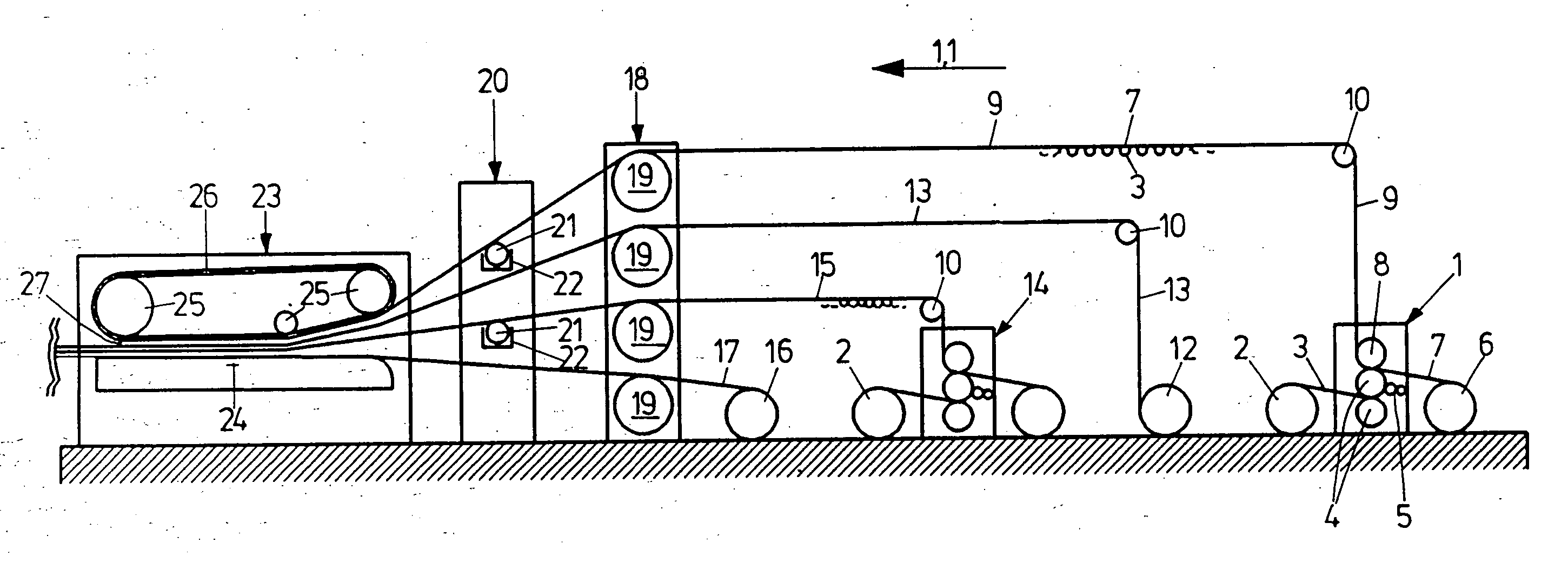
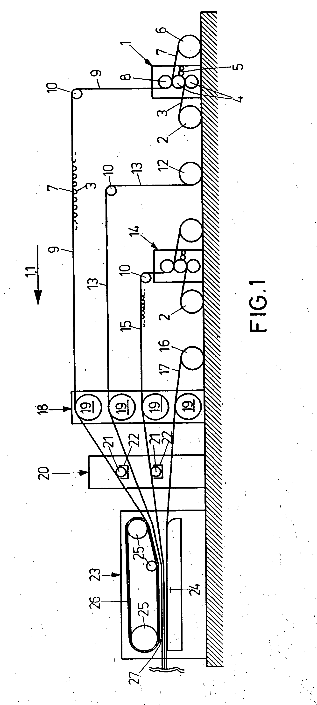
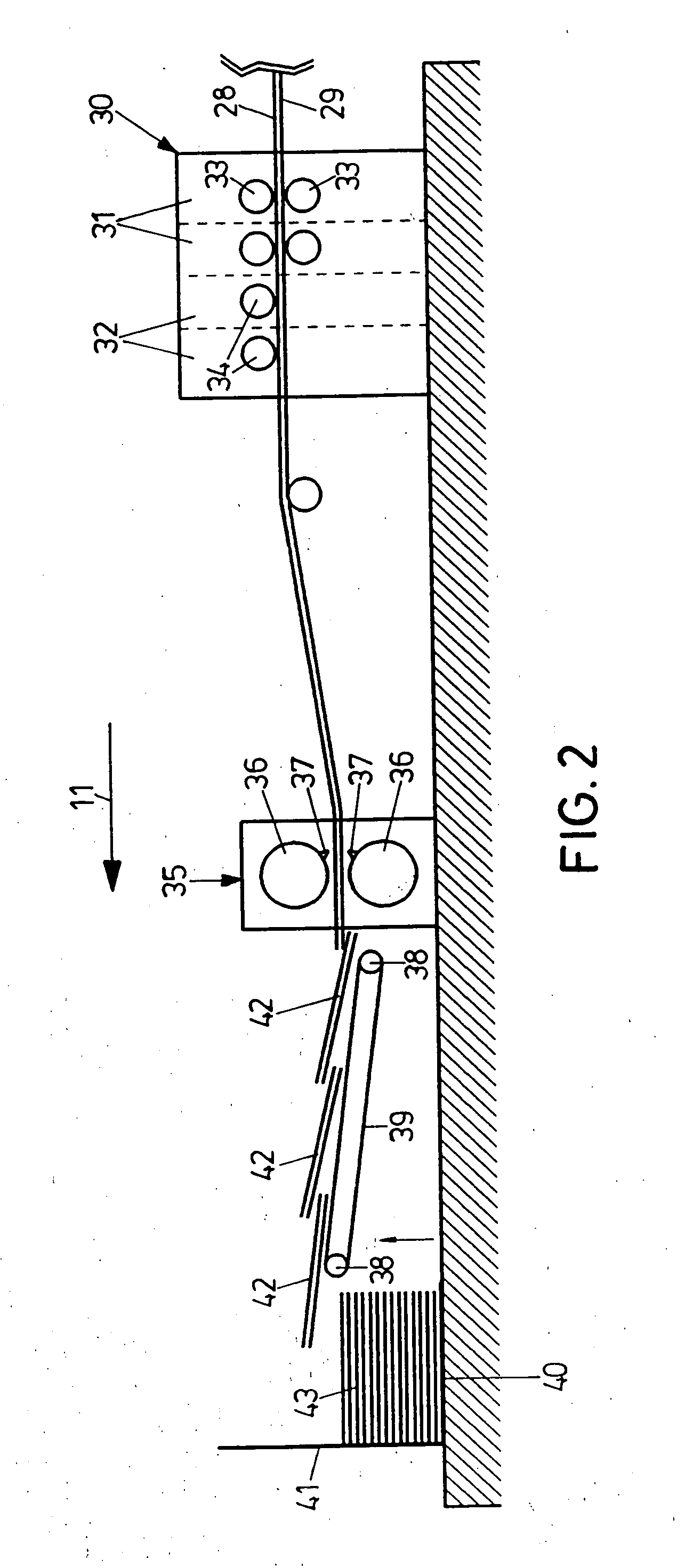
[0013] The following is a description of a first embodiment of the invention with reference to FIGS. 1 to 3. A corrugating machine, which is diagrammatically outlined in FIGS. 1 and 2, comprises a machine 1 for the manufacture of single-faced corrugated board. The machine 1 has an unroll stand 2 for a medium 3 which, for a corrugation to be produced, is passed between two neighboring fluted rollers 4. Then the tips of the corrugated medium 3 are glued in an adhesive applicator unit 5 and the corrugated medium 3 and a backer 7 from an unroll stand 6 are pressed together and joined in a nip between a nip roller 8 and a fluted roller 4. A single-faced corrugated board is discharged upwards from the machine 1 and deviated by a deflection roller 10 in a working direction 11. The machine 1 for the manufacture of single-faced corrugated board is generally known, for instance from U.S. Pat. No. 5, 632,850, GB 2,305,675 A, or DE 43 05 158 A1, which reference is made to for any details.

[0014...


PUM


Abstract

A corrugating machine for the manufacture of sheets of corrugated board comprises a first manufacturing unit for the production of a first web of corrugated board, a second manufacturing unit for the production of a second web of corrugated board, a mounting unit, which is disposed downstream of the manufacturing units in a working direction, for non-adhesively bringing together the first web of corrugated board and the second web of corrugated board and a working unit, which is disposed downstream of the mounting unit, for jointly working the first web of corrugated board and the at least second web of corrugated board that lie on top of each other.

Description

[0001] This is a continuation of copending parent application Ser. No. 10 / 235,941, filed Sep. 6, 2002.BACKGROUND OF THE INVENTION [0002] 1. Field of the Invention [0003] The invention relates to a corrugating machine for the manufacture of sheets of corrugated board. [0004] 2. Background Art [0005] Corrugating machines for the manufacture of single-faced corrugated board or multi-layered corrugated board have been known for quite a while, for instance from U.S. Pat. No. 5,632,850. The output of a corrugating machine can be raised by increasing the velocity of the corrugated board. However, there are upper limits to this. If a further increase in production is intended, another separate corrugating machine must be made available. SUMMARY OF THE INVENTION [0006] It is an object of the invention to embody a corrugating machine of raised manufacturing capacity. [0007] The object is attained in a corrugating machine for the manufacture of sheets of corrugated board, comprising a first ma...

Claims


Application Information

Patent Timeline
IPC IPC(8): B31F1/28
CPCB31F1/2813Y10T156/1016Y10T156/1025B31F1/2822
Inventor TITZ, FELIX
Owner BHS CORRUGATED MASCHEN & ANLAGENBAU
Learn More