
In-vehicle image display system

a display system and vehicle technology, applied in the field of vehicle image display system, can solve the problems of unfavorable cost and design, inability to view images from the tv in the front seat while images from the dvd in the rear seat, etc., and achieve the effect of preventing deterioration in user usability, high speed for transmitting image signals, and optimizing the system

Inactive Publication Date: 2005-06-23
DENSO CORP
View PDF8 Cites 23 Cited by
  • Summary
  • Abstract
  • Description
  • Claims
  • Application Information

AI Technical Summary

Benefits of technology

[0006] It is an object of the present invention to provide an in-vehicle image display system that is capable of having difference in a display image between a front-seat display device and a rear-seat display device, under a simple system structure.
[0008] In the above structure, the primary display device does not need to include an image-drawing unit for the second display device. This enables a simple system structure to cause the primary display device and the secondary display device to display the images different from each other, respectively. Further, this is favorable in costs and designing.
[0010] In this structure, each of the first display device and the second display device includes a storing unit and a display control unit that are necessary for displaying images on a respective display unit. When only one of the two display devices is installed, the only one device therefore includes the minimum components for displaying the images. As a result, not only when multiple display devices are installed, but also when only one display device is installed, the system can be optimized. Further, installing a dedicated line that dedicatedly communicates signals relating to image data between the first and second display devices enables a high speed for transmitting the image signals. Thus, for instance, a menu window for manipulating apparatuses can be rapidly displayed, which can prevent deterioration in user's usability.

Problems solved by technology

That is, it is impossible that images from the TV are viewed in the front-seat while images from a DVD are viewed in the rear seat.
However, this method requires an image drawing device for the rear-seat display device regardless of whether a rear-seat display device is disposed or not, complicating a structure of the front-seat display device.
Further, it is unfavorable in costs and designing.

Method used


Image

  • In-vehicle image display system
  • In-vehicle image display system
  • In-vehicle image display system

Examples


first embodiment

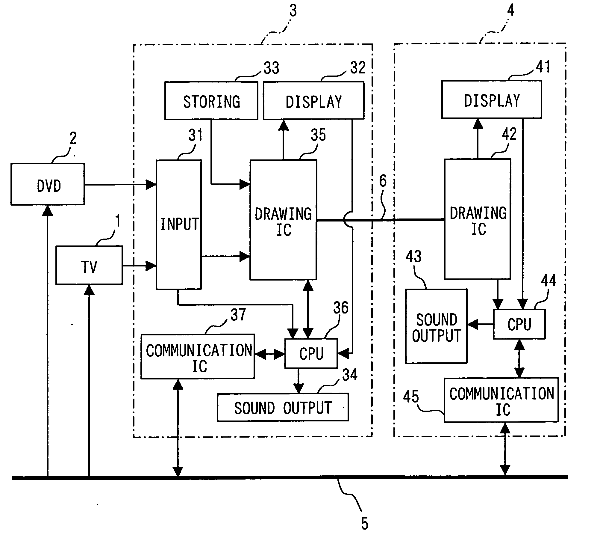
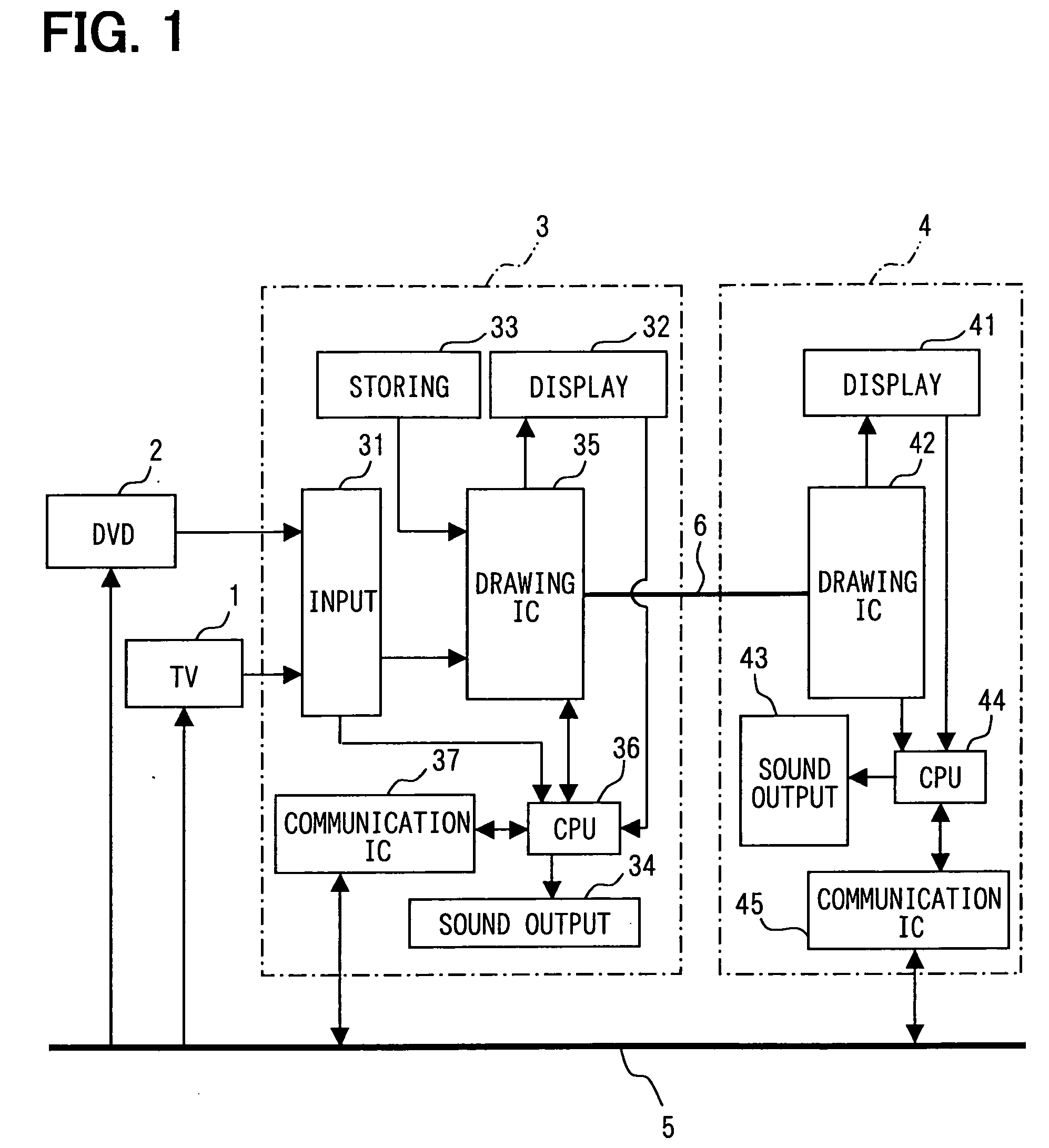
[0025] The present invention is directed to an in-vehicle image display system as a first embodiment. The in-vehicle image display system is operated by being interfaced with an image apparatus mounted in a vehicle. As shown in FIG. 1, the system uses a car navigation device 3 as a front-seat display and a rear-seat display device 4 as a rear-seat display. These devices 3, 4, a TV tuner 1, and a DVD player 2 interface with each other via an in-vehicle local area network (LAN) 5 in the vehicle, to thereby communicate manipulation signals, request signals, sound data, etc. under a simple structure using the LAN 5. The car navigation device 3 interfaces with the rear-seat display device 4 via a dedicated line 6. The car navigation device 3 obtains image data outputted from the TV tuner 1 and the DVD player 2 to forward the obtained image data to the rear-seat display device 4 via the dedicated line 6.

[0026] The TV tuner 1 and the DVD player 2 will be explained below. The TV tuner 1 in...

second embodiment

[0081] An in-vehicle image display system according to a second embodiment of the present invention will be explained with reference to FIGS. 11, 12, 13. As shown in FIG. 11, in the second embodiment, an image-output apparatus such as a TV tuner 1 and a DVD player 2 interfaces with the system only via an in-vehicle LAN 105. That is, image data outputted from the image-output apparatus is transmitted via the in-vehicle LAN, in addition to a manipulation signal from a car navigation device 103 or a rear-seat display device 104, which differentiates this embodiment from the first embodiment.

[0082] Here, a menu window is stored in an image-data storing device 133 in the car navigation device 103, to thereby be read by an image-drawing IC 135. Therefore, the menu window can be rapidly displayed not only when displayed on a touch display 132 in the car navigation device 103 but also when displayed on a touch display 141 in the rear-seat display device 104.

[0083] As shown in FIG. 12 that...


PUM


Abstract

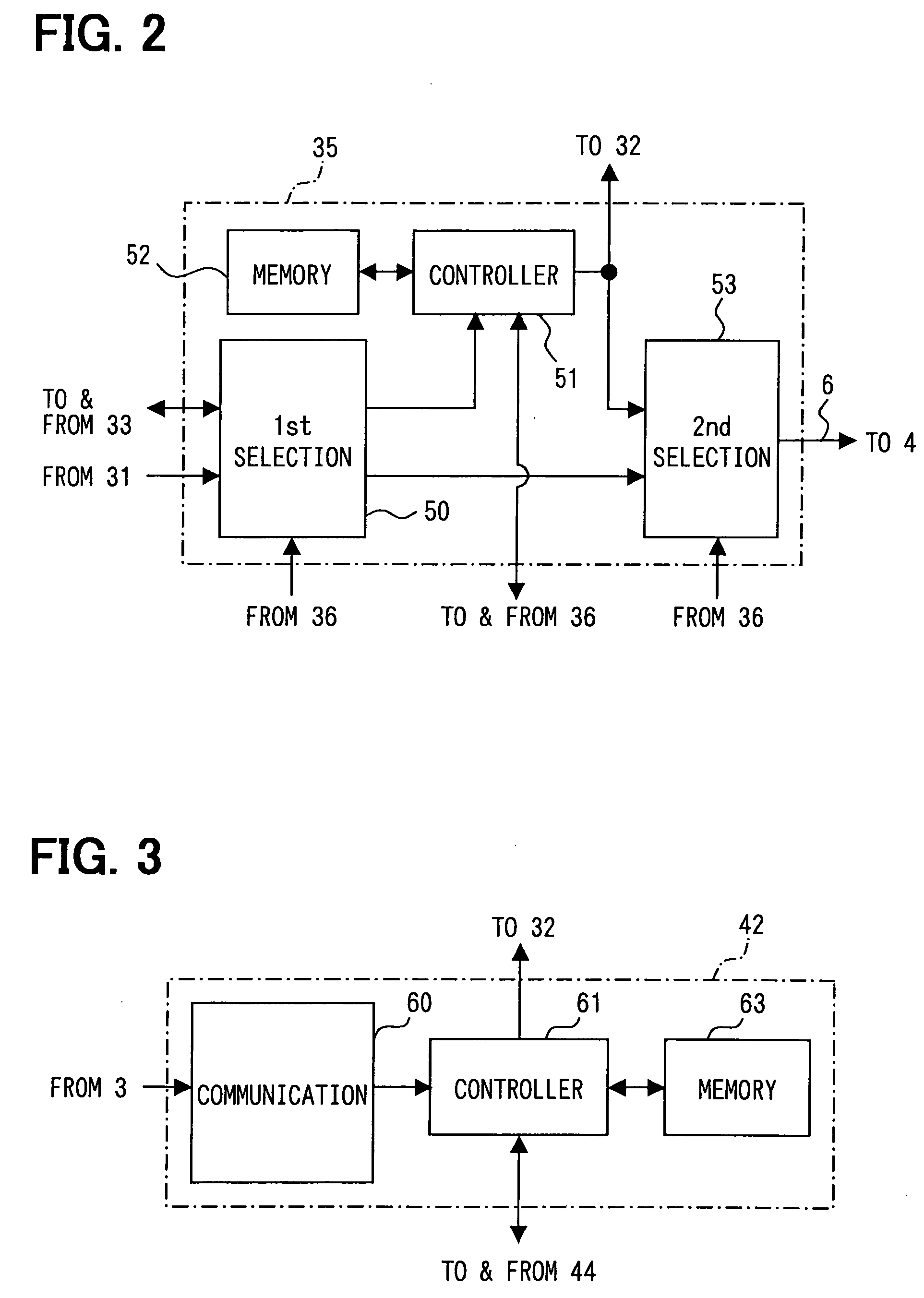
In an in-vehicle image display system, each of a car navigation device and a rear-seat display device includes an own image-drawing IC. The car navigation device interfaces with a TV tuner and a DVD player. When receiving a request signal from the rear-seat display device, the car navigation device forwards relevant image data to the rear-seat display device using a dedicated line. The rear-seat display device converts the forwarded image data to image signals using the own image-drawing IC to thereby display them. Thus, the car navigation device and the rear-seat display device can display different display window images with a simple system structure where no image-drawing IC used for the rear-seat display device is provided within the car navigation device.

Description

CROSS REFERENCE TO RELATED APPLICATIONS [0001] This application is based on and incorporates herein by reference Japanese Patent Applications No. 2003-421543 filed on Dec. 18, 2003 and No. 2004-332403 filed on Nov. 16, 2004. FIELD OF THE INVENTION [0002] The present invention relates to an in-vehicle image display system that displays images outputted from multiple devices mounted on a vehicle. BACKGROUND OF THE INVENTION [0003] There is a vehicle that is equipped with not only a display for a front seat but also a display for a rear seat. For instance, a known in-vehicle display system can provide images from an in-vehicle device not only to an occupant in the front seat but also to an occupant in the rear seat. [0004] In this system, a front-seat display device displays image data outputted from a TV tuner or the like; further, a rear-seat display device interfacing with the front-seat display device displays the image data that is displayed on the front-seat display device by obt...

Claims


Application Information

Patent Timeline
Patent Type & Authority Applications(United States)
IPC IPC(8): H04N5/64B60R11/02H04N5/775H04N5/85H04N7/16H04N7/24H04N21/414H04N21/436
CPCH04N5/775H04N5/85H04W88/02H04N21/41422H04N21/43615H04N7/163
Inventor SETO, OHISA
Owner DENSO CORP
Learn More