Adaptive observer and related method

a technology of observer and observer, applied in the field of adaptive observer, can solve the problems of limiting the applicability of the domain of filter needed to satisfy the spr condition, limiting the adaptive law of both approaches to adapting only the nn output layer, etc., and achieve the effect of improving the performan

Inactive Publication Date: 2005-06-23
GEORGIA TECH RES CORP
View PDF6 Cites 77 Cited by
  • Summary
  • Abstract
  • Description
  • Claims
  • Application Information

AI Technical Summary

Benefits of technology

[0007] In another more detailed embodiment of the invention, the adaptive observer comprises an error observer, first and second neural network units, and a time delay unit. The error observer is coupled to receive a tracking error signal z that is a difference between an estimated output signal ŷ and an actual output signal y of an observed system. The error observer generates an estimated adaptive error signal Ê based on the tracking error signal z. The error observer can be implemented as a linear filter. The first and second neural network units can each comprise nonlinearly parameterized neural networks. The first neural network unit is coupled to receive the estimated adaptive error signal Ê and adjusts its input and output connection weights {circumflex over (M)}fT, {circumflex over (N)}fT based on the estimated adaptive error signal Ê. Likewise, the second neural network unit is coupled to receive the estimated adaptive error signal Ê and adjusts its input and output connection weights MgT, NgT based on the estimated adaptive error signal Ê. The time delay unit is coupled to receive the actual output signal y and generates at least one delayed value yd of the actual output signal y which the time delay unit provides as a vector signal μ to the first and second neural network units as an input. The first and second neural network units generate respective adaptive signals {circumflex over (M)}fTσ({circumflex over (N)}fTμ) and {circumflex over (M)}gTσ({circumflex over (N)}gTμ) based on the vector signal μ and respective connection weights {circumflex over (M)}fT, {circumflex over (N)}fT, {circumflex over (M)}gT, {circumflex over (N)}gT. The adaptive signals {circumflex over (M)}fTσ({circumflex over (N)}fTμ) and {circumflex over (M)}gTσ({circumflex over (N)}gTμ) are provided to the linear observer to improve its performance in the presence of nonlinearity in the observed system. The time delay unit can further receive a control signal u, generate at least one delayed value ud thereof, and output the delayed value ud to the first and second neural network units as part of the vector signal μ.

Problems solved by technology

However, these approaches impose assumptions that severely limit their domain of applicability.
The main challenge lies in defining an error signal for updating the neural network connection weights.
However, the filter needed to satisfy the SPR condition may not always exist, particularly for systems with multiple outputs.
The adaptive laws in both approaches are limited to adapting only the NN output layer weights.

Method used


Image

  • Adaptive observer and related method
  • Adaptive observer and related method
  • Adaptive observer and related method

Examples


Embodiment Construction

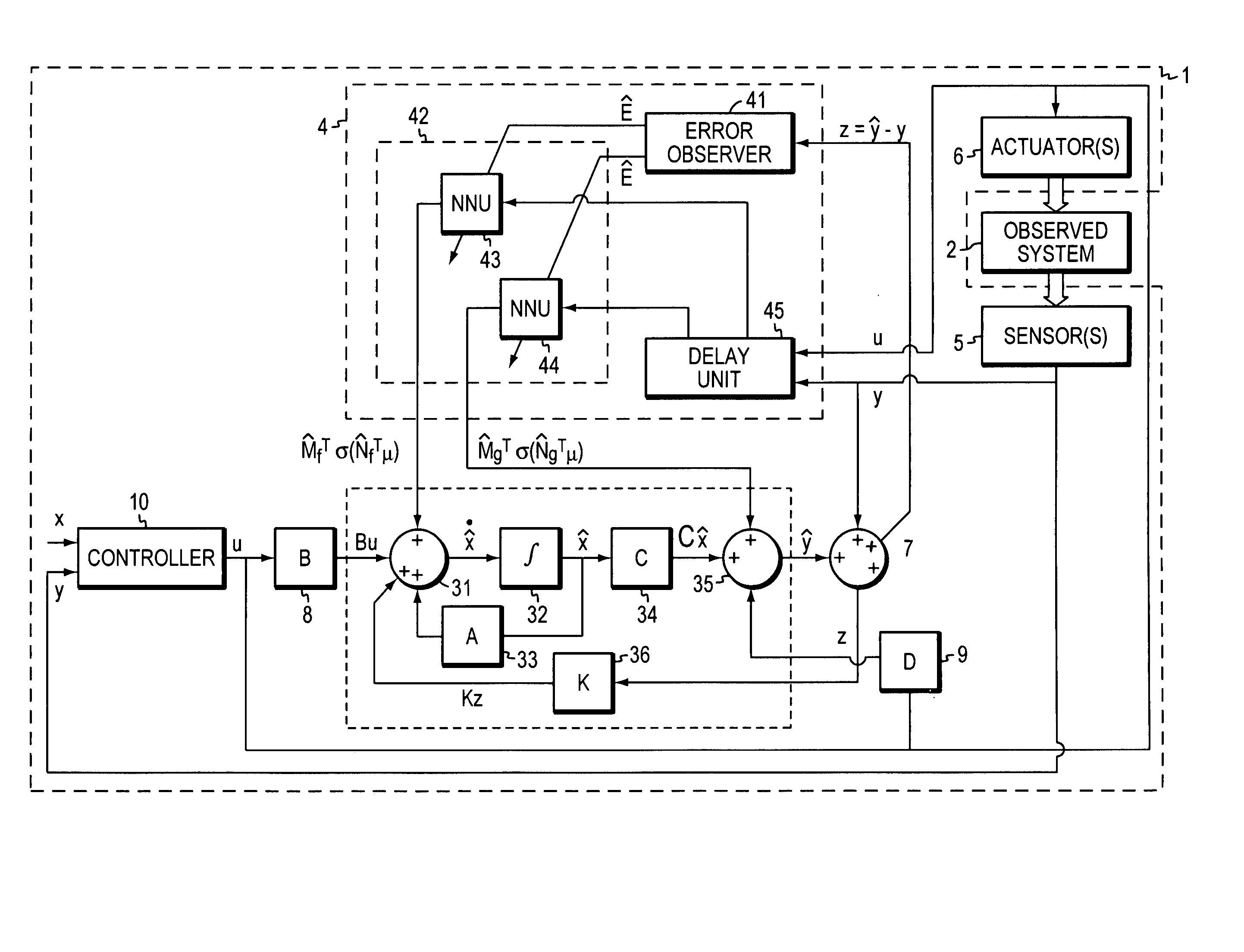
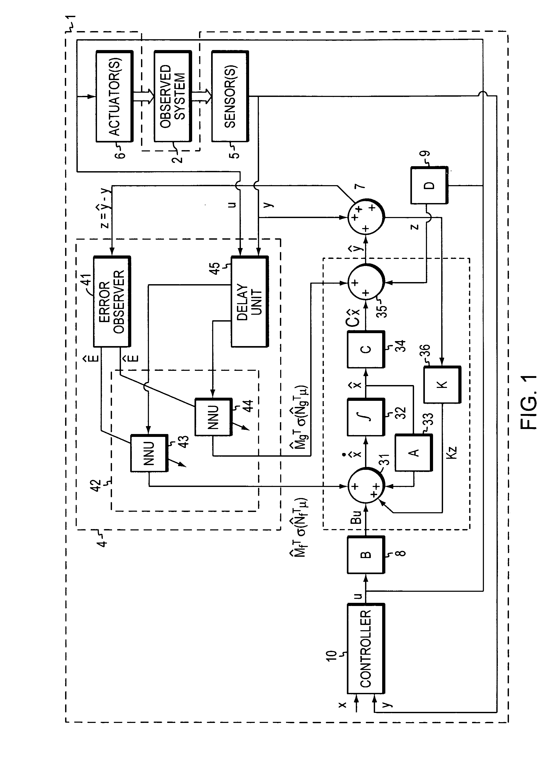
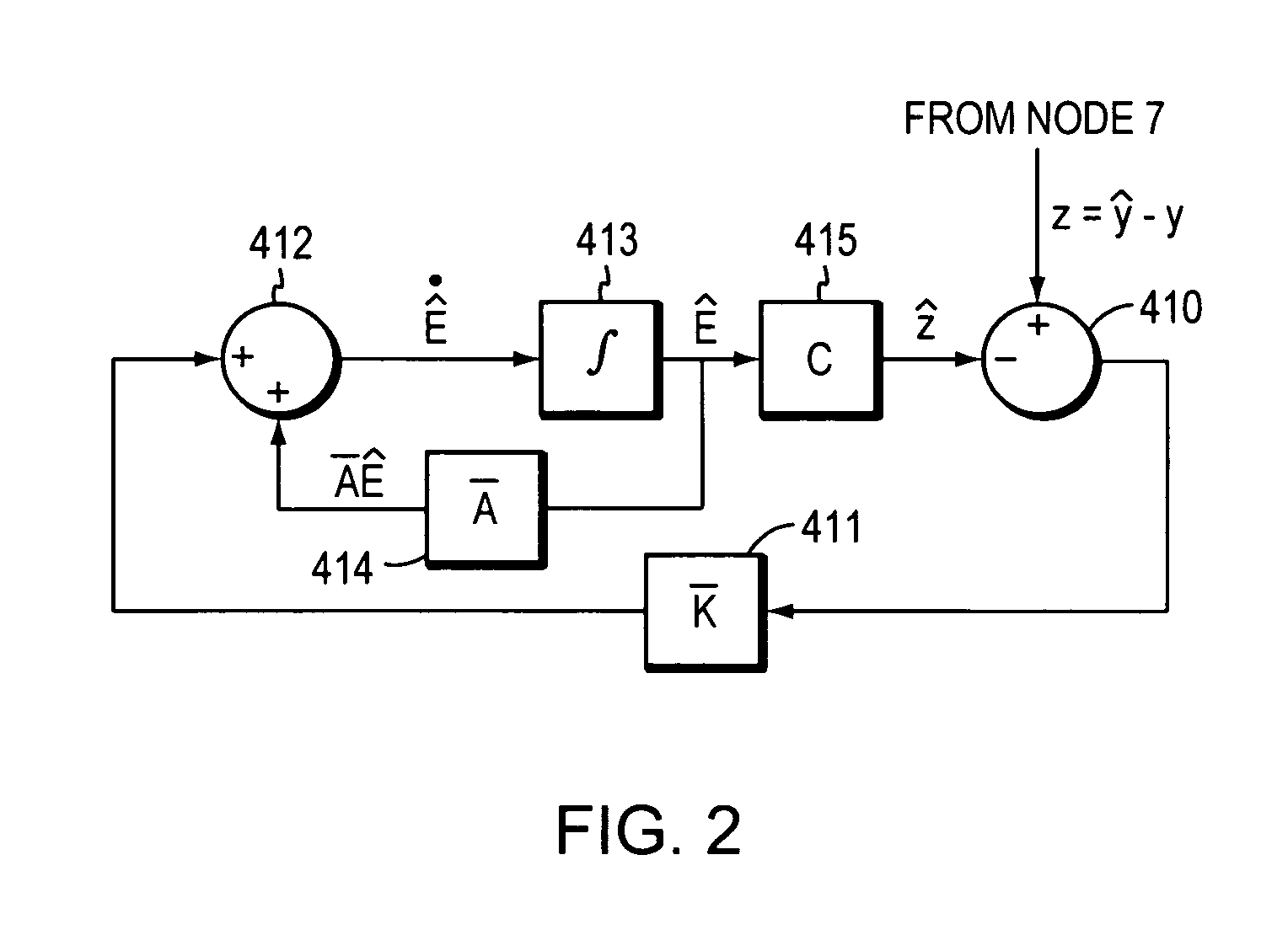
[0017] The present invention now will be described more fully hereinafter with reference to the accompanying drawings, in which some, but not all embodiments of the inventions are shown. Indeed, this invention may be embodied in many different forms and should not be construed as limited to the embodiments set forth herein; rather, these embodiments are provided so that this disclosure will satisfy applicable legal requirements. Like numbers refer to like elements throughout.

GLOSSARY OF TERMS

[0018] As used herein, the following terms have the following definitions:

[0019]‘Actuator’ can be virtually any device capable of affecting the state of an observed system to control a degree of freedom thereof. Such actuator can be a part of an aircraft, spacecraft, vehicle, ship, robot, machine, or other system to be tracked.

[0020]‘Control Cycle’ refers to a single iteration or execution of a software program by a processor implementing a tracking system in generating the various signals r...


PUM


Abstract

A disclosed apparatus comprises an adaptive observer that has an adaptive element to augment a linear observer to enhance its ability to control a nonlinear system. The adaptive element comprises a first, and optionally a second, nonlinearly parameterized neural network unit, the inputs and output layer weights of which can be adapted on line. The adaptive observer generates the neural network units' teaching signal by an additional linear error observer of the nominal system's error dynamics. The adaptive observer has the ability to track an observed system in the presence of unmodeled dynamics and disturbances. The adaptive observer comprises a delay element incorporated in the adaptive element in order to provide delayed values of an actual output signal and a control signal to the neural network units.

Description

CROSS-REFERENCE TO RELATED APPLICATIONS [0001] This application claims priority benefits under 35 U.S.C. 119(e) to U.S. provisional application No. 60 / 510,504 filed Oct. 9, 2003 and U.S. provisional application No. 60 / 528,557 filed Dec. 9, 2003, both naming Anthony J. Calise, Naira Hovakimyan, and Venkatesh K. Madyastha as inventors. Both such provisional applications are incorporated herein by reference as if set forth in full herein.STATEMENT OF U.S. GOVERNMENT RIGHTS IN THE INVENTION [0002] This invention was made with U.S. Government funding under contract no. F49620-01-1-0024 awarded by AFOSR. The U.S. Government has certain rights in the invention.FIELD OF THE INVENTION [0003] The present invention is generally directed to system, apparatus, and method used to track, and optionally control, a system under observation. More specifically, the present invention is directed to a class of tracking systems that uses an adaptive observer to determine the error between an actual outpu...

Claims


Application Information

Patent Timeline
Patent Type & Authority Applications(United States)
IPC IPC(8): G05B13/02G05B13/04
CPCG05B13/04G05B13/027
Inventor HOVAKIMYAN, NAIRACALISE, ANTHONYMADYASTHA, VENKATESH
Owner GEORGIA TECH RES CORP
Why Eureka
Try Eureka