
Weather strip

a weather strip and weather strip technology, applied in the field of weather strips, can solve the problems of warp production of weather strips and worse installation workability, and achieve the effect of increasing rigidity and easy fitting

Inactive Publication Date: 2005-06-23
TOYODA GOSEI CO LTD
View PDF9 Cites 3 Cited by
  • Summary
  • Abstract
  • Description
  • Claims
  • Application Information

AI Technical Summary

Benefits of technology

[0008] An object of the invention made in view of the circumstances above is to provide a weather strip feasible for reducing the number of man-hours, restraining the generation of a warp and improving installation workability.
[0011] According to the means 1, the first seal member and the second seal member are coupled via the coupling portion, so that the number of man-hours necessary for the manufacture of them is reducible in comparison with a case where they are separately molded. At the time of installation, moreover, it is less burdensome to install the first seal member and the second seal member in comparison with a case where they are installed independently of each other, whereby an improvement in workability is attempted. The greater part or the whole part of the second fitting base portion is formed of the solid material or the fine foaming material according to the means 1. Consequently, the installed condition as a whole can be maintained with stability by relatively securely installing the first seal member by relatively securely latching one side portion of the second fitting base portion even without securely latching the other side portion on the first seal member side. Therefore, the installation work is greatly simplified by adopting an installation mode like this.
[0012] According to the means 1, moreover, though the greater part or the whole part of the second fitting base portion is formed of the solid material or the fine foaming material, at least part of the first fitting base portion is also formed of the solid material or the fine foaming material. Hence, unlike the prior art in which the difference in not only foaming rate but expansion rate may cause a warp to be produced, the presence of the solid material or the fine foaming material in the first seal member and the second member both causes the difference in expansion rate to hardly occur. Therefore, it is possible to prevent nonconformity such as a deterioration in installation workability resulting from the generation of the warp and consequently the installation workability can greatly be improved.
[0024] In the weather strip according to each of the means above, wherein the foaming material and the solid material or the fine foaming material are intermingled, there develops a problem arising from deteriorating external appearance because of difference in external appearance mode. In view of this, as the surface region visually confirmable from the outside in the installed condition is totally formed of the foaming material according to the means 6, a difference in the external appearance mode hardly occurs, thus resulting in preventing the deterioration of the quality of the external appearance.
[0027] Assuming that a number of installation errors exist in each of the means for installing the first fitting base portion and the second fitting base portion, such errors can be absorbed. Consequently, the installation workability is prevented from being deteriorated and even after the installation, the stabilization of the installed condition can be attempted.
[0029] According to the means 8, the first fitting base portion is latched by the clip. Of the first fitting base portion, the part unaffected by incorporating the clip is formed of the solid material or the fine foaming material, whereby the operation / working-effect become effective. Further, the clip is relatively easily fitted as the part affected by incorporating the clip, or the periphery of the part where the insertion of the clip is made is formed of the foaming material. Moreover, the presence of the solid material or the fine foaming material results in increasing rigidity, whereby sealing between the weather strip and an opposing part (e.g., a door frame) is further stabilized.

Problems solved by technology

When the weather strip is thus configured, however, the difference in foaming rate between the main seal member and the sub-seal member and the difference in expansion rate therebetween may cause a warp to be produced in the weather strip in case both the members are integrally molded.
Consequently, the weather strip may warp immediately after the extrusion (at the time of vulcanization and the like), so that the installation workability may be worsened instead.

Method used


Image

  • Weather strip
  • Weather strip
  • Weather strip

Examples


Embodiment Construction

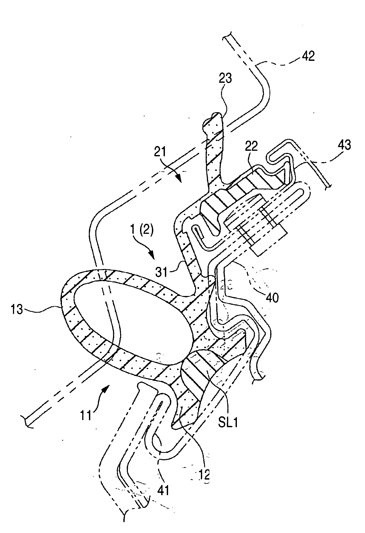
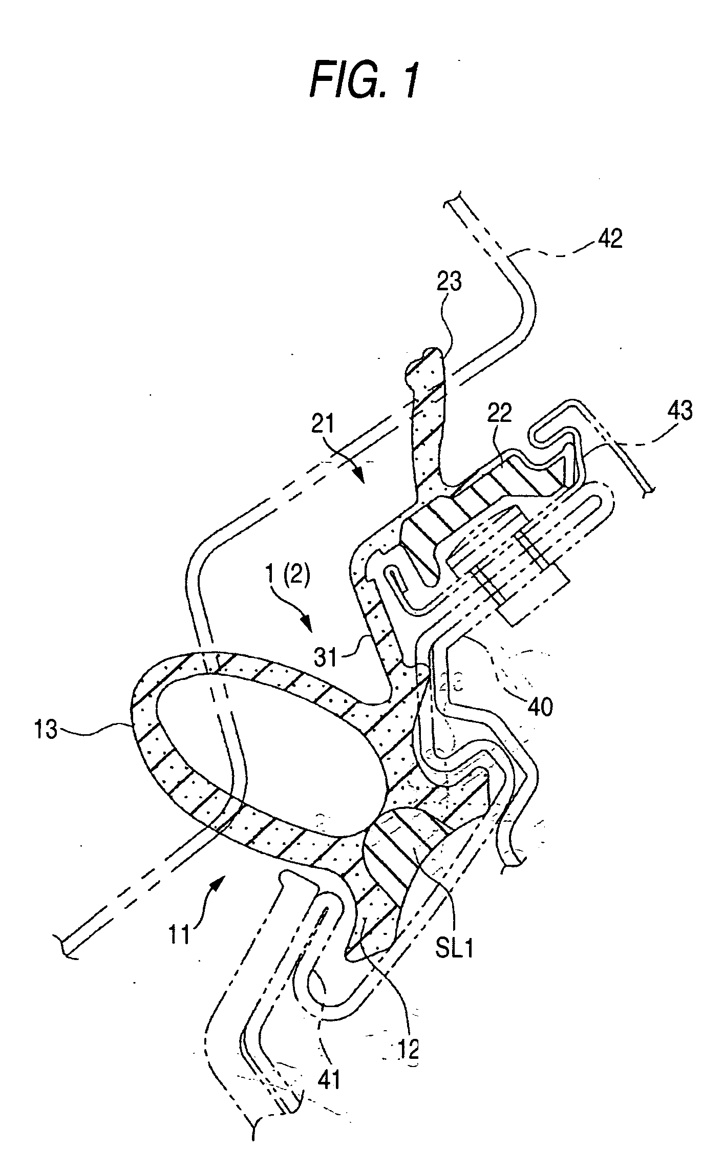
[0034] An embodiment of the invention will now be described by reference to the drawings.

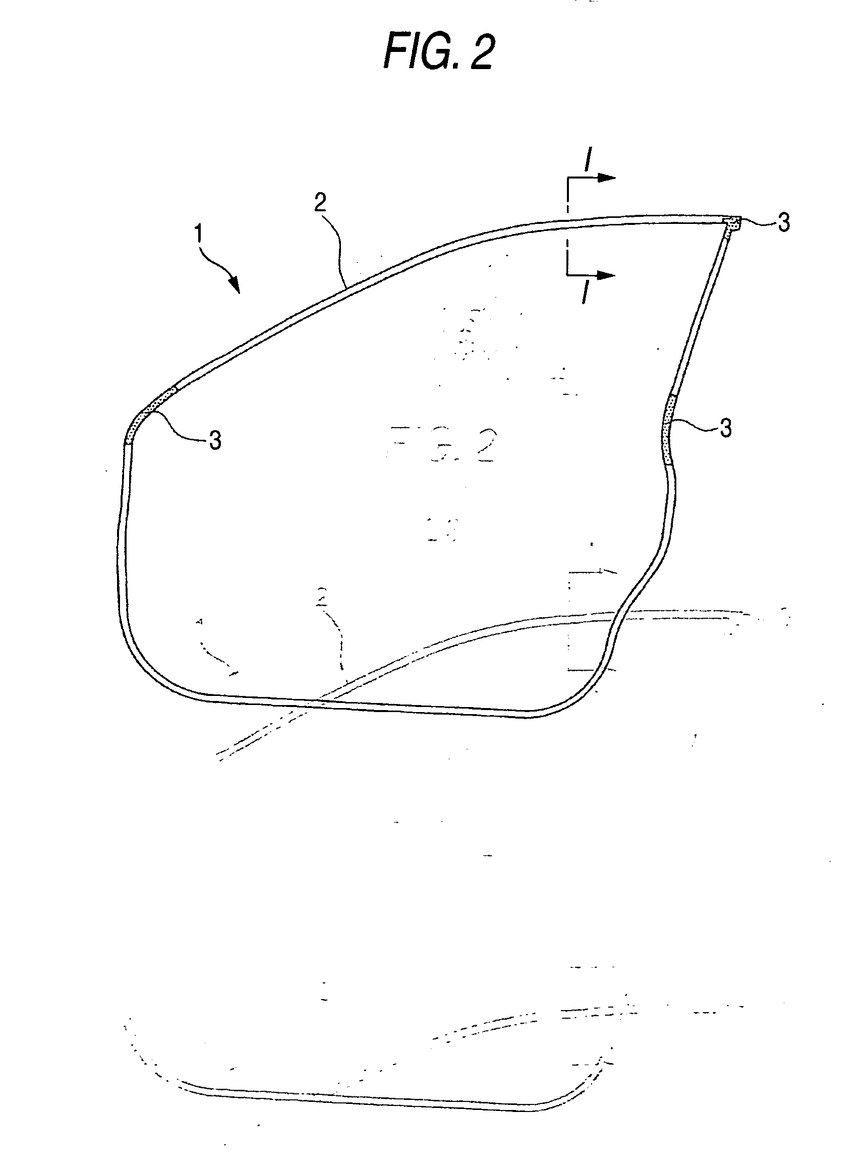
[0035] Automobiles are provided with open-and-close front doors and a weather strip 1 is installed along the outer periphery of such a front door as shown in FIG. 2. The greater part of the weather strip 1 along the longer direction is formed by an extrusion molding portion 2. Moreover, corner portions (with point patterns in FIG. 2) are formed with die-molded sections 3.

[0036] As a portion corresponding to the roof side portion (upper side portion of FIG. 2) out of the extrusion-molded portion 2 has a distinctive feature according to the embodiment of the invention, the construction of the portion in question will be described as follows.

[0037] As shown in FIG. 1, the extrusion-molded portion 2 in the upper side portion has a main seal member 11 as a first seal member, a sub-seal member 21 as a second seal member and a coupling portion 31 for coupling both the seal members 11 and 21.

[0038] ...


PUM


Abstract

An extrusion-molded portion in the upper side portion of a weather strip is provided with a main seal member, a sub-seal member and a coupling portion. The main seal member has a first fitting base portion in the form of a substantially flat plate fitted to the first retainer of a door frame, and a hollow seal portion formed integrally with the first fitting base portion. The sub-seal member has a second fitting base portion in the form of a substantially flat plate fitted to a second retainer, and a seal lip. The seal lip, the coupling portion and the hollow seal portion are consecutively formed by monolithic molding with EPDM sponge rubber. The greater part of the second fitting base portion and the central part of the first fitting base portion are formed of EPDM solid rubber. Therefore, the difference in expansion rate hardly occurs and a warp is restrained from being generated.

Description

BACKGROUND OF THE INVENTION [0001] 1. Field of the Invention [0002] The present invention relates to a weather strip applied to the joints of an automobile door or a roof side, for example. [0003] 2. Related Art [0004] Weather strips are installed around the outer peripheral edges of automobile doors and the like. Heretofore, a weather strip having a hollow seal portion (main seal portion) and a weather strip having a seal lip (sub-seal portion) maybe applied to respective parts corresponding to the upper side of a door. In this case, these two pieces of weather strips have to be produced separately from each other and installed independently of each other. [0005] On the other hand, the art of integrating a main seal member having the main seal portion with a sub-seal member having the sub-seal portion by means of a coupling portion has been proposed (see Japanese Patent Publication No. JP-A-2002-307952, for example). With this arrangement, the number of man-hours necessary for the ...

Claims


Application Information

Patent Timeline
CPCB60J10/0005B60J10/0062Y10T428/24008Y10T428/13B60J10/08B60J10/16B60J10/30B60J10/80
Inventor AOKI, SHIGENORISUZUKI, SATOSHIMORITA, TAKAFUMIYOSHIOKA, SHINICHI
Owner TOYODA GOSEI CO LTD
Learn More