
Mirror device for vehicle

a mirror device and vehicle technology, applied in the direction of mirrors, mountings, instruments, etc., can solve the problems of shrinkage and warping on the surface of the mirror, insufficient strength of the support shaft portion b>116/b> of the case b>114/b>, and insufficient strength of the support shaft portion, so as to achieve effective control of vibration generated at the mirror main body portion

Inactive Publication Date: 2005-06-23
KK TOKAI RIKA DENKI SEISAKUSHO
View PDF11 Cites 7 Cited by
  • Summary
  • Abstract
  • Description
  • Claims
  • Application Information

AI Technical Summary

Benefits of technology

The present invention provides a door mirror device for vehicles that can effectively control vibration without increasing the plate thickness of the support shaft portion. It also improves the durability of case convexities and stand concavities. Additionally, it provides an electrically powered folding mirror device with a stand and a support shaft, and a transmission mechanism for swinging the case and mirror unit when the motor is operated. The invention also includes a positioning mechanism for holding the case and mirror unit at different positions. Overall, the invention enhances the performance and reliability of vehicle mirror devices.

Problems solved by technology

However, the strength of the support shaft portion 116 of the case 114 may be insufficient.
However, if this is done, there is the possibility that problems will be caused such as the generation of shrinkage and warping on a surface of the mirror.
Also, it may be necessary to increase the number of cycles in the production process, leading to increased production costs.
However, with this type of door mirror device, the worm gear is press-inserted onto the motor output shaft, and is not movable in an axial direction with respect to the motor output shaft.
As a result, there is a problem that the motor output shaft receives a sliding force from the worm gear, and this reduces the life span of the motor.
However, in this type of device, there is a tendency for the worm gear to displace in a perpendicular direction with respect to the motor output shaft.
As a result, the sound of the operation between the worm gear and the helical gear becomes very loud and in some cases the worm gear may skid.
As a result, the case convexities, the stand concavities, the insertion convexities and the insertion concavities become worn and the durability of the mirror device is poor.
Since two sets of the case convexities and stand concavities are arranged on the same circle, whose center is the support shaft, when the end portions of the case convexities are engaged with the end portions of the stand concavities, the pressure which both the case convexities and the stand concavities receive is large and thus durability is poor.
Also, when the end portions of the case convexities are engaged with the end portions of the stand concavities, the case member may rattle on the stand and as a result the mirror also tends to rattle.

Method used


Image

  • Mirror device for vehicle
  • Mirror device for vehicle
  • Mirror device for vehicle

Examples


first embodiment

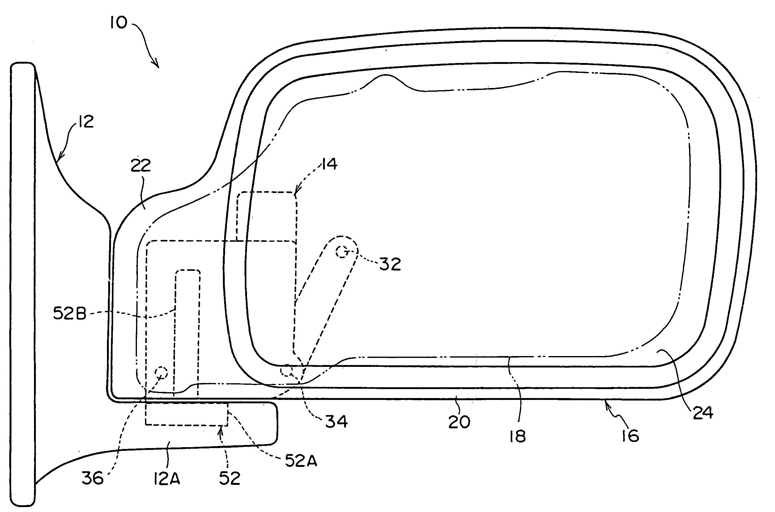
[0056] An electrically powered housable-type door mirror device 10 according to a first embodiment of the present invention will be described with reference to FIGS. 1 to 5.

[0057]FIG. 5 outlines the electrically powered housable-type door mirror device 10 according to this first embodiment in an assembled state. The door mirror device 10 is fixed at a predetermined position to a side of a vehicle body. The door mirror device 10 is comprised of a door stay 12 which is a “door mirror base portion” and extends in a substantially lateral direction of the vehicle, an electrically powered housing unit 14 which swings between a housed position and a position for viewing and is axially supported by a rotation shaft 52B (described hereinafter), which rotation shaft 52B is erected from an extending portion 12A of the stay 12, and a mirror main body portion 16 which swings integrally with the electrically powered housing unit 14.

[0058] The mirror main body 16 includes: a frame 18 which has a...

second embodiment

[0083] A door mirror device 210 according to a second embodiment of the present invention will be described with reference to FIGS. 6 to 9.

[0084] The mirror device 210 includes a housing mechanism 212 and the housing mechanism 212 is provided with a stand 214. The stand 214 is fixed to a stay (not shown), which is fixed to a vehicle door or the like. A cylindrical support shaft 216 is provided integrally with the stand 214 so as to be erect, and the support shaft 216 is fixed via the stand 214 to a side of the vehicle body. A gear plate 218 is disposed around the support shaft 216, and rotation of the gear plate 218 with respect to the support shaft 216 is blocked.

[0085] The housing mechanism 212 includes a case 220 and a cover 221 which covers an upper opening portion of the case 220. The support shaft 216 is inserted through the case 220 and thus the case 220 is rotatably supported by the support shaft 216. The case 220 is connected to a mirror (not shown) for viewing the rear d...

third embodiment

[0102] Lastly, a door mirror device for a vehicle according to a third embodiment of the present invention will be described with reference to FIGS. 10 to 17.

[0103] A door mirror device 310 includes a housing mechanism 312. A stand 314 is provided to the housing mechanism 312. The stand 314 is fixed to a mirror stay (not shown) which is fixed to a vehicle door. The stand 314 is provided integrally with a cylindrical support shaft 316 so as to be erect. The support shaft 316 is fixed by the stand 314 to a side of the vehicle body.

[0104] As shown in detail in FIG. 10, on the stand 314, there are a plurality of different circles (2 in the present embodiment). A plurality of stand concavities 318 (2 for each circle and thus a total of 4 in the present embodiment) are provided around a center which is at the support shaft 316. Both end portions of each stand concavity 318 project to the upper side (referred to as the case 322 side hereinafter), and, as shown in detail in FIG. 11, are f...


PUM


Abstract

A foldable mirror device for a vehicle, in which a case is mounted on a support shaft erected from a base. The case includes a ring-shaped support portion for supporting the shaft, a motor connected to a transmission for swinging the mirror, and a clutch portion for disengageably engaging with the base. The support portion can be strengthened by ribs between the support portion and other portions of the case. A worm gear of the transmission can be mounted on a motor output shaft to be freely movable therealong, and supported and constrained by supporting a bottom end of the worm gear on the case and accommodating an upper end of the worm gear in a cylindrical projection from a motor base which supports the motor. End portions of convexities and concavities at the engagement portion can be formed in a concave or convex screw shape.

Description

BACKGROUND OF THE INVENTION [0001] 1. Field of the Invention [0002] The present invention relates to a mirror device for a vehicle. [0003] 2. Description of the Related Art Prior Art 1 [0004] In a mirror device for a vehicle, such as an electrically powered housable-type door mirror device, a mirror stay is fixed to a side of the vehicle body so as to extend in a substantially transverse direction from the vehicle, and a mirror main body portion is supported by the mirror stay such that the mirror main body can swing between a housed position and a position for viewing. This type of conventional door mirror device 100 is illustrated in FIGS. 18 to 21 and a brief description thereof follows. [0005] As illustrated in FIG. 18, a stand 104 whose axial direction is a substantially vertical direction of the vehicle, is fixed on a mirror stay 102 which is fixed at a side of the vehicle. An electrically powered housing unit 106 is provided on the rotation shaft 104A of the stand 104, so as...

Claims


Application Information

Patent Timeline
Patent Type & Authority Applications(United States)
IPC IPC(8): B60R1/074B60R1/076
CPCB60R1/072B60R1/076B60R1/074
Inventor YOSHIDA, SHIGEKI
Owner KK TOKAI RIKA DENKI SEISAKUSHO
Learn More